

LED driving circuit having a large operational range in voltage
- Summary
- Abstract
- Description
- Claims
- Application Information
AI Technical Summary
Benefits of technology
Problems solved by technology
Method used
Image

Examples
first embodiment
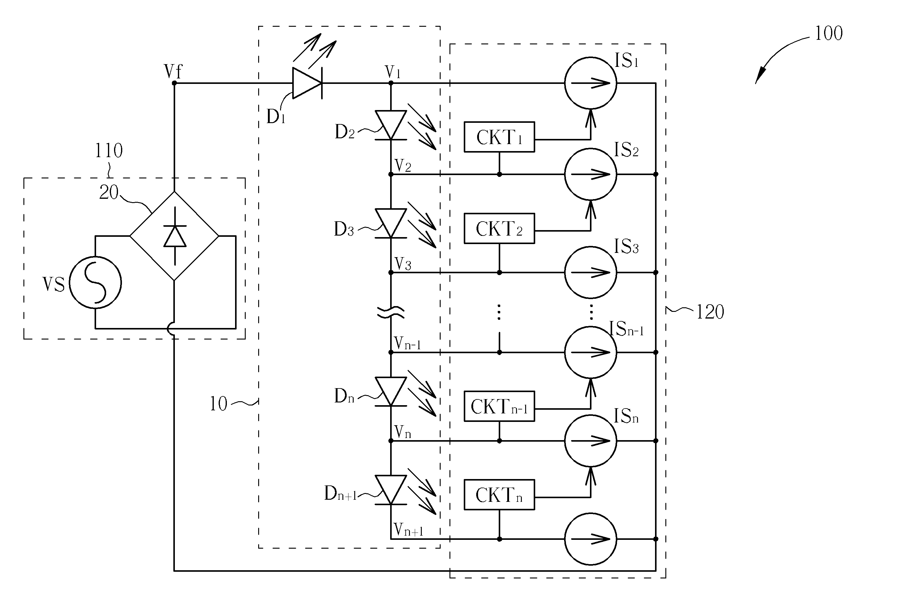
[0019]In the LED driving circuit 100 according to the present invention, the current-selecting circuit 120 includes a plurality of variable current sources IS1-ISn and a plurality of adjusting circuits CKT1-CKTn. The variable current sources IS1-ISn provide adjustable current limits, based on which the currents flowing through the corresponding luminescent units D1-Dn are regulated at respective predetermined values, thereby providing brightness control and device protection. The adjusting circuits CKT1-CKTn can respectively detect the values of the voltages V1-Vn, thereby adjusting the current limits of the variable current sources IS1-ISn accordingly.
[0020]As previously illustrated, the driving voltage Vf periodically varies with time. For illustration, assume that the driving voltage Vf gradually rises from 0 after initialization. When the voltage established across the luminescent unit D1 exceeds the threshold voltage of the luminescent unit D1, the luminescent unit D1 is turned...
second embodiment
[0022]In the LED driving circuit 200 according to the present invention, the current-selecting circuit 220 includes a plurality of constant current sources IS1-ISn, a plurality of switches SW1-SWn and a plurality of judging units CM1-CMn. The current sources IS1-ISn provide constant current limits, based on which the currents flowing through the corresponding luminescent units D1-Dn are regulated at respective predetermined values, thereby providing brightness control and device protection. Each of the switches SW1-SWn includes a first end coupled between two corresponding adjacent luminescent units among the luminescent units D1-Dn (respectively denoted by V1-Vn), and a second end coupled to a corresponding current source among the current sources IS1-ISn. The judging units CM1-CMn can respectively detect the values of the voltages V1-Vn, thereby turning on / off the corresponding switches SW1-SWn accordingly.
[0023]As previously illustrated, the driving voltage Vf periodically varies...
PUM
 Abstract
Description
Claims
Application Information