

Wireless power receiving terminal and wireless charging system
- Summary
- Abstract
- Description
- Claims
- Application Information
AI Technical Summary
Benefits of technology
Problems solved by technology
Method used
Image

Examples
first embodiment
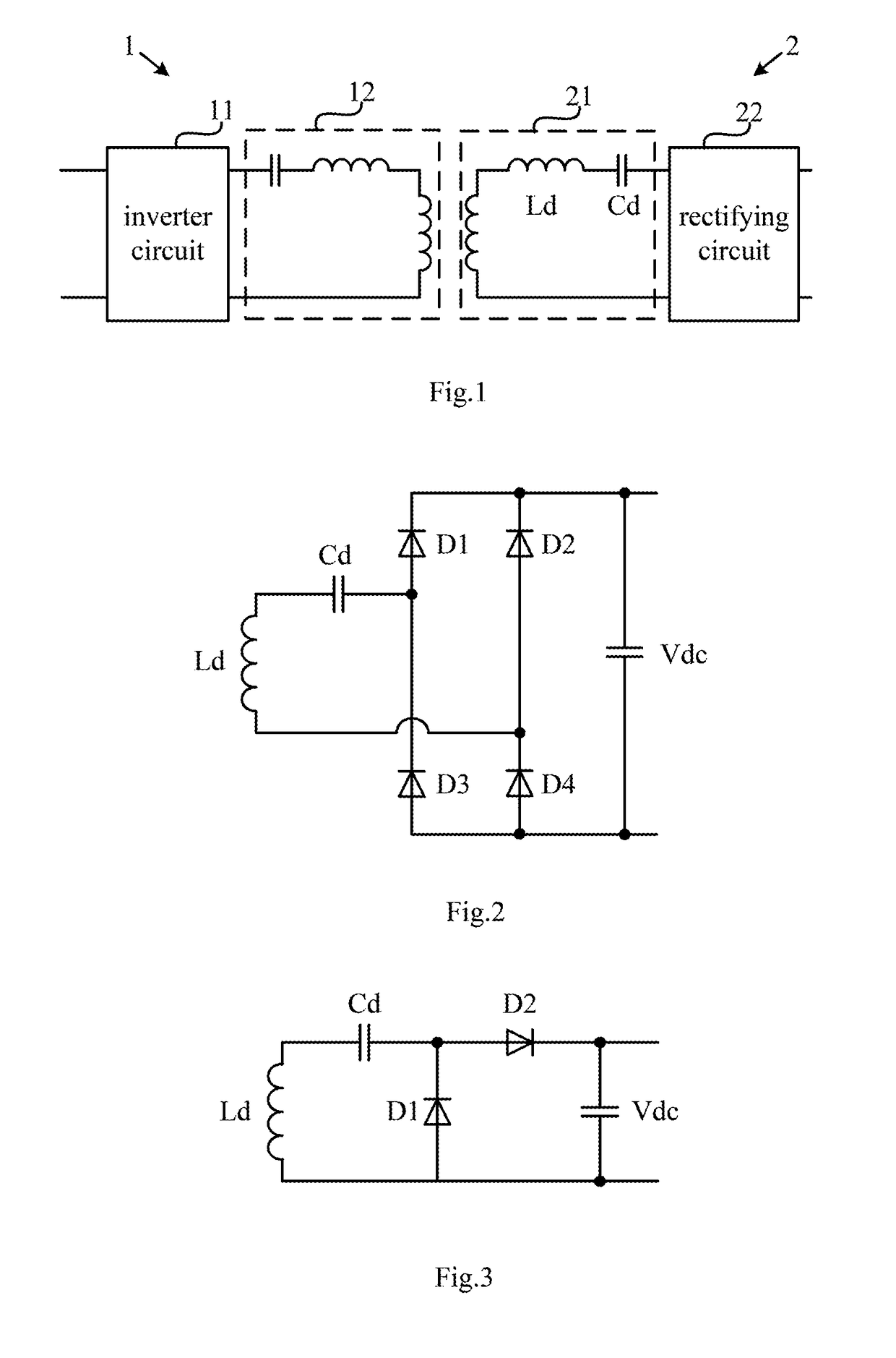
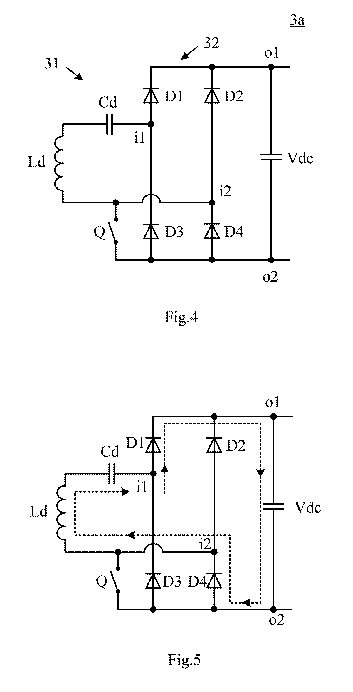
[0043]FIG. 4 is a circuit diagram of a wireless power receiving terminal according to the present disclosure. As shown in FIG. 4, the wireless power receiving terminal 3a of the present embodiment comprises a receiving-side resonant circuit 31, a full-bridge rectifying circuit 32 and a switch Q. Among them, the receiving-side resonant circuit 31 is configured to be coupled with a transmitting-side resonant circuit of a corresponding wireless power transmitting terminal (not shown in the Figure) in a non-contact manner so as to wirelessly receive power. The receiving-side resonant circuit 31 may comprise a receiving coil Ld. In one embodiment, the receiving-side resonant circuit 31 further comprises a receiving capacitance Cd in series with the receiving coil Ld, both of which form a series resonant circuit which can resonate in response to an alternating magnetic field of a frequency that is a predetermined operation frequency f0 to output an alternating current. In another embodime...
third embodiment
[0051]FIG. 10 is a circuit diagram of a wireless power receiving terminal according to the present disclosure. As shown in FIG. 10, in the wireless power receiving terminal 3c of this embodiment, the switch Q is connected between the port i1 of the input ports and the port o1 of the output ports of the full-bridge rectifying circuit 32. When the switch Q is turned off, the full-bridge rectifying circuit 32 operates normally. When the switch Q is turned on, a current loop of the coil Ld, the capacitance Cd, the switch Q, the output capacitance Vdc and the diode D4 is formed during the positive half cycle of the alternating current. A current loop of the coil Ld, the diode D2, the switch Q and the capacitance Cd is formed during the negative half cycle of the alternating current. The alternating current generated by the resonance charges the capacitance Cd during the negative half cycle of the alternating current. The voltage across the capacitance Cd and the voltage generated by the ...
fourth embodiment
[0052]FIG. 11 is a circuit diagram of a wireless power receiving terminal according to the present disclosure. As shown in FIG. 11, in the wireless power receiving terminal 3d of this embodiment, the switch Q is connected between the port i2 of the input ports and the port o1 of the output ports of the full-bridge rectifying circuit 32. When the switch Q is turned off, the full-bridge rectifying circuit 32 operates normally. When the switch Q is turned on, a current loop of the coil Ld, the capacitance Cd, the diode D1 and the switch Q is formed during the positive half cycle of the alternating current, and the capacitance Cd is charged by the voltage generated by the resonance. A current loop of the capacitance Cd, the coil Ld, the switch Q, the output capacitance Vdc and the diode D3 is formed during the negative half cycle of the alternating current. The voltage across the capacitance Cd and the voltage generated by the resonance simultaneously supply power to the output ports. T...
PUM
 Abstract
Description
Claims
Application Information