Moving object detection apparatus and moving object detection method

Inactive Publication Date: 2011-04-21
SOVEREIGN PEAK VENTURES LLC
View PDF7 Cites 32 Cited by
  • Summary
  • Abstract
  • Description
  • Claims
  • Application Information

AI Technical Summary

Benefits of technology

[0012]A second objective of the present invention is to solve the problem associated with the amount of calculation in Non-Patent Reference 1. Thus, the present invention is to solve these two problems, and an objective of the present invention is to

Problems solved by technology

However, Patent Reference 1 described above has a problem that the moving object cannot be accurately extracted especially in a scene, like a street, where moving objects such as people come and go.
Here, when the candidate region is not accurately extracted, it is impossible to correctly apply, to the candidate region, the parameterized model that corresponds to such a target moving object.
Especially in a crowded scene, it is difficult to accurately extract the candidate region.
Moreover, even when the candidate region is accurately extracted, the present method still has a problem as follows.
That is to say, a huge number of parameters are required for parameterizing such a target object to obtain a model.
This may result in an incorrect matching of the model to the candidate region.
Therefore, the region extraction cannot be accurately performed when the method disclosed in Patent Reference 1 is employed.
In oth

Method used


Image

  • Moving object detection apparatus and moving object detection method
  • Moving object detection apparatus and moving object detection method
  • Moving object detection apparatus and moving object detection method

Examples


first modification

of First Embodiment

[0139]A moving object detection apparatus in the first modification of the first embodiment according to the present invention is explained as follows.

[0140]The present modification describes an example of a case where the segmentation into subsets is performed according to a method different from the method used in the first embodiment.

[0141]The moving object detection apparatus in the first modification has the same configuration as the one described in the first embodiment, except that the segmentation unit 103 performs different processing. Therefore, the explanation about the same components is omitted here.

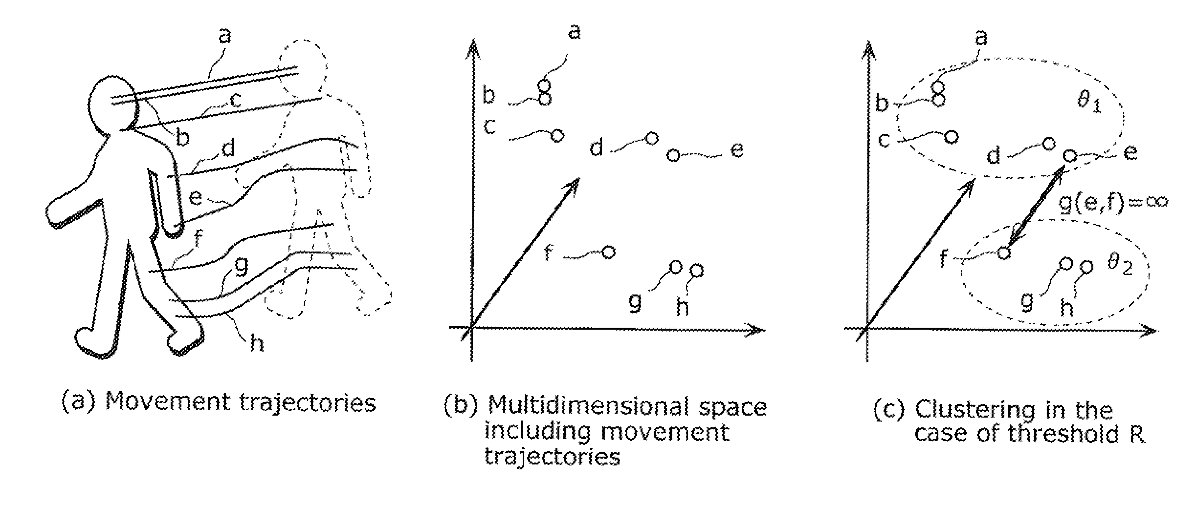
[0142]As mentioned, the present modification is different from the first embodiment in the processing performed by the segmentation unit 103. In the first embodiment above, as shown in FIG. 5, the position space of the image 401 is divided into the P number of subsets 402. In the present modification, movement trajectories as represented by Expression 2 in...

second modification

of First Embodiment

[0151]A moving object detection apparatus in the second modification of the first embodiment according to the present invention is explained as follows.

[0152]The present modification describes an example of a case where the region extraction unit 107 performs region extraction according to a method different from the method used in the first embodiment.

[0153]The moving object detection apparatus in the second modification has the same configuration as the one described in the first embodiment, except that the region extraction unit 107 performs different processing. Therefore, the explanation about the same components is omitted here.

[0154]As mentioned, the present modification is different from the first embodiment in the processing performed by the region extraction unit 107. More specifically, the region extraction unit 107 performs dimensionality reduction on a geodesic distance matrix and then executes clustering on the movement trajectories in the lower dime...

third modification

of First Embodiment

[0193]A moving object detection apparatus in the third modification of the first embodiment according to the present invention is explained as follows.

[0194]The present modification describes an example of a case where criteria are set for the region extraction explained in the first embodiment, and candidates for the region extraction are accordingly generated. Then, the region extraction is achieved by selecting, from among the generated candidates, the candidate having the number closest to a predetermined number of moving objects.

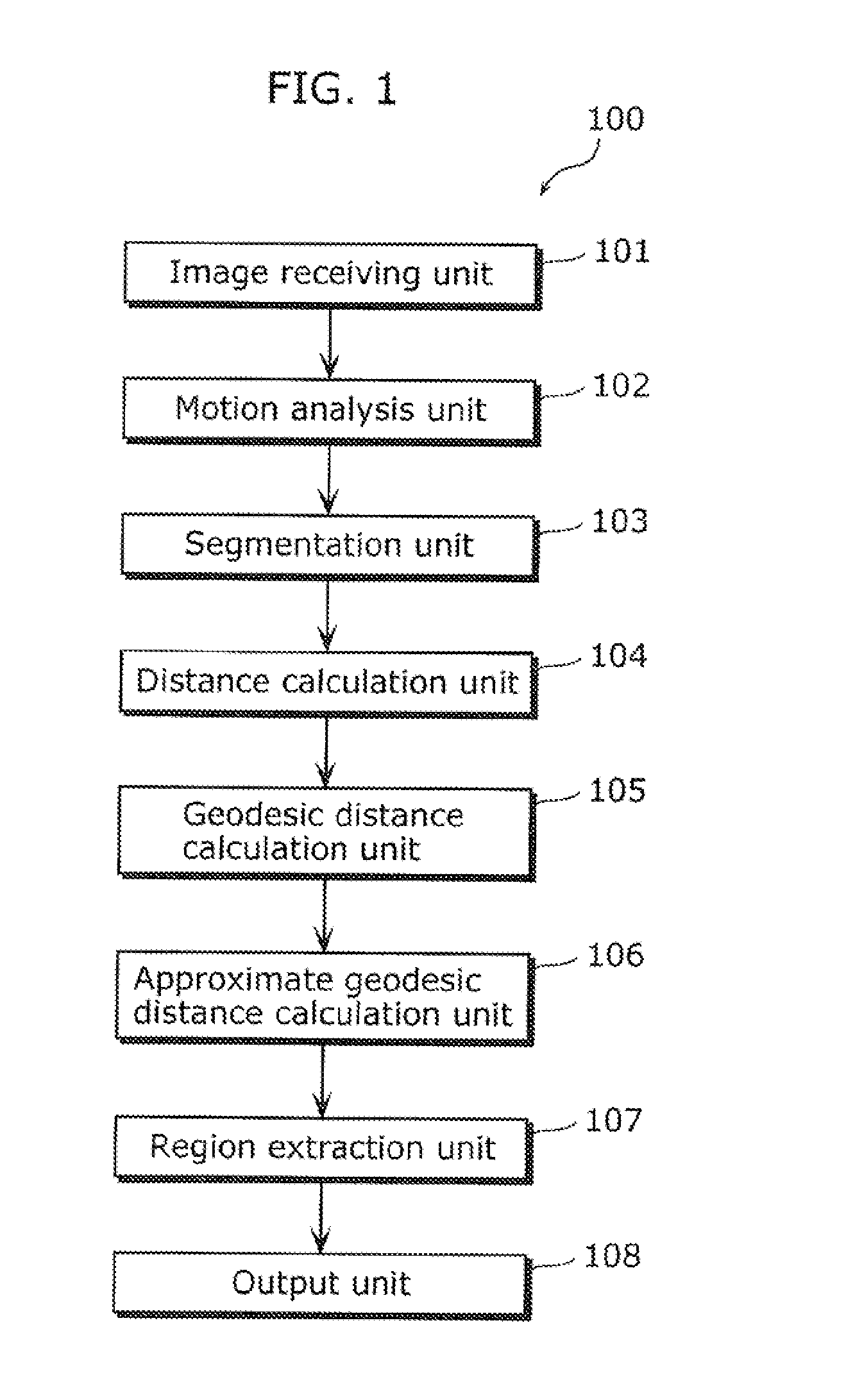
[0195]FIG. 15 is a diagram showing a configuration of a moving object detection apparatus 100a in the third modification of the first embodiment. As shown in FIG. 15, the moving object detection apparatus 100a includes an image receiving unit 101, a motion analysis unit 102, a segmentation unit 103, a distance calculation unit 104, a geodesic distance transformation unit 105a, an approximate geodesic distance calculation unit 106a, a ...


PUM


Abstract

To provide a moving object detection apparatus which accurately performs region extraction, regardless of the pose or size of a moving object. The moving object detection apparatus includes: an image receiving unit receiving the video sequence; a motion analysis unit calculating movement trajectories based on motions of the image; a segmentation unit performing segmentation so as to divide the movement trajectories into subsets, and setting a part of the movement trajectories as common points shared by the subsets; a distance calculation unit calculating a distance representing a similarity between a pair of movement trajectories, for each of the subsets; a geodesic distance calculation unit transforming the calculated distance into a geodesic distance; an approximate geodesic distance calculation unit calculating an approximate geodesic distance bridging over the subsets, by integrating geodesic distances including the common points; and a region extraction unit performing clustering on the calculated approximate geodesic distance.

Description

CROSS REFERENCE TO RELATED APPLICATION[0001]This is a continuation application of PCT application No. PCT / JP2010 / 004378 filed on Jul. 5, 2010, designating the United States of America.BACKGROUND OF THE INVENTION[0002](1) Field of the Invention[0003]The present invention relates to apparatuses which detect a moving object in an image, and particularly relates to an apparatus which detects a moving object in a video sequence including images by performing region extraction to determine a region showing the whole or a part of the moving object such as a person that moves and changes shape in the video sequence, on the basis of motion information on the moving object.[0004](2) Description of the Related Art[0005]As a method of detecting a moving object such as a person that moves and changes shape or extracting an image region including the moving object, there is a combination of techniques to extract a candidate region showing a target moving object from an image and to apply a previo...

Claims


Application Information

Patent Timeline
IPC IPC(8): G06K9/00
CPCG06T7/2006G06T7/2093G06T2207/30241G06T2207/20021G06T2207/30196G06T2207/10016G06T7/215G06T7/292
Inventor IWASAKI, MASAHIRONOBORI, KUNIO
Owner SOVEREIGN PEAK VENTURES LLC
Why Eureka
Try Eureka