Supercharge Your Innovation With Domain-Expert AI Agents!

Right angle twisted pair connector

a technology of twisted pair and connector, which is applied in the direction of cable termination, electric cable installation, coupling device connection, etc., can solve the problems of cable not meeting the requirements of the category 5e specification, cable may not be shielded, and the amount of cable can be bent adjacent to the connector is limited

Active Publication Date: 2011-05-12
INFINITE ELECTRONICS INT INC
View PDF26 Cites 15 Cited by
  • Summary
  • Abstract
  • Description
  • Claims
  • Application Information

AI Technical Summary

Benefits of technology

[0062]Another advantage of the present invention is that it can help minimize or eliminate alien cross-talk between twisted pairs of two adjacent cables. For instance, as patch panels and the like continue to accommodate more and more densely packed cable connections, alien cross-talk can become a problem. The connector configuration of the present invention can be used to assure that the twisted pairs in each of the adjacent cables enter the channels in the connector in the same layout, e.g., the two wires for channel 1 is always the leftmost two wires in the connector, so that, in a side by side cable layout, the same channels of each cable are maximally spaced from each other.

Problems solved by technology

Most Cat 5 cables in use today are unshielded, relying on the twisted pair design for noise rejection.
If the wires of the twisted pairs are unraveled (i.e., untwisted) over even a very short distance at the end of a cable for purposes of connecting the wires to the contacts in the terminating plug, the cable may not meet the requirements of the Category 5e specification.
Generally, the amount by which the cable can be bent adjacent the connector is limited by the properties of the cable and any overmold and / or strain relief placed over the cable adjacent the connector
Furthermore, the cable and its connector are vulnerable to separation or electrical discontinuity in one or more wires due to the sharp flex at the point of entry of the cable into the connector body.
Too sharp of a bend in the wires of a twisted pair also can adversely affect signal quality in the cable.
These phenomena make it difficult to manufacture a twisted pair cable with a right angle connector with a short radius bend.

Method used


Image

  • Right angle twisted pair connector
  • Right angle twisted pair connector
  • Right angle twisted pair connector

Examples


Embodiment Construction

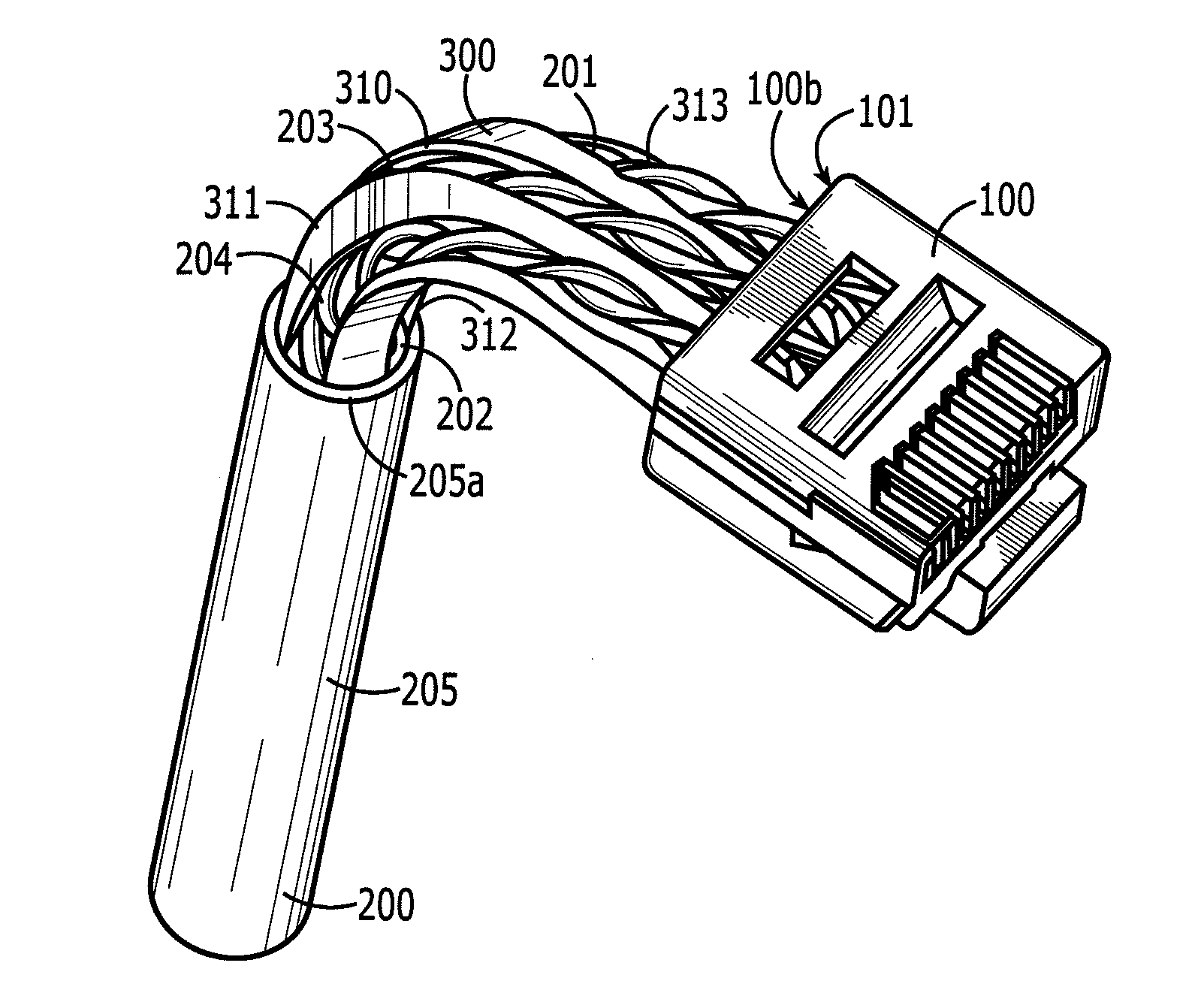
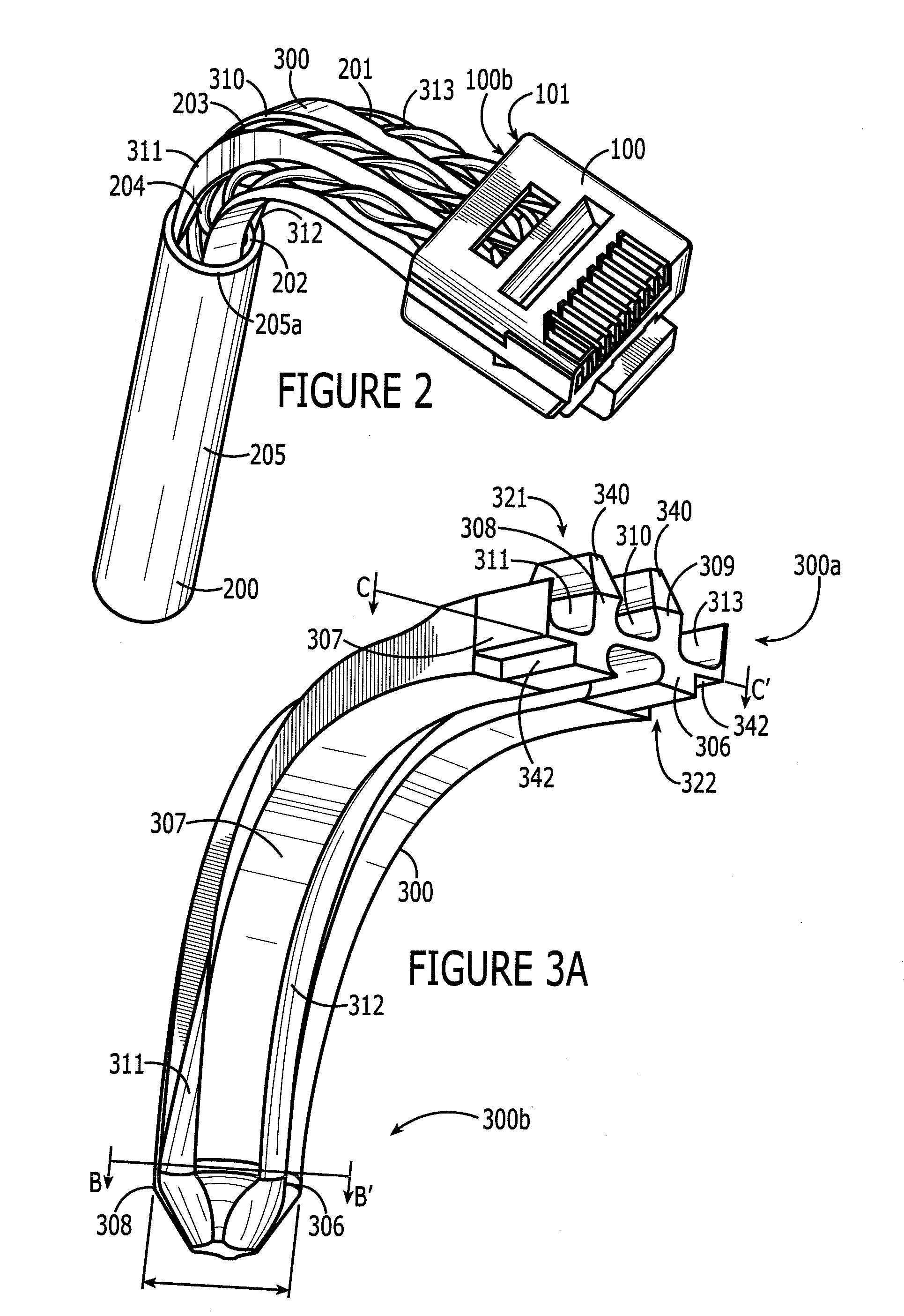
[0030]FIG. 1 is a perspective view of an exemplary short form factor RJ-45 plug body 100 that might be placed on the end of a twisted pair cable. This connector may be used to terminate a twisted pair cable, such as Category 5, Category 5e, and Category 6 cables. As used herein, “twisted pair cable” refers to any cable including one or more twisted pairs. By “short form factor”, it is meant that the space in between the front and rear faces 100a, 100b of the connector body 100 is less than the average RJ-45 form factor.

[0031]RJ-45 plugs are available on the market in many different designs, of which the design shown and described in FIG. 1 and herein below is only one such design for exemplary purposes. As will become clear from the following discussion, the principles of the present invention can be applied in connection with virtually any connector body and any twisted pair cable.

[0032]Also, terms such as “front” and “rear” or “proximal” and “distal” as used herein are used relati...


PUM


Abstract

The invention relates to a twisted pair cable and connector combination comprising a cable having a plurality of twisted pairs, each twisted pair comprising a first conductor and a second conductor, an electrical connector having an electrical connection element for each conductor of the cable and a window through which the conductors of the cable enter the connector, wherein each conductor in the cable is electrically coupled to a one of the electrical connection elements in the electrical connector, and a guide element disposed adjacent the window for guiding the twisted pairs into the connector, the guide element having a distal end and a proximal end and a length there between, the guide element curved over the length and including at least one channel running along the length of the guide element body for each twisted pair, the guide element gradually transitioning over the length from a first cross sectional shape wherein said channels are disposed in a pattern relative to each other corresponding to the relative positions of the twisted pairs in the cable to a second cross sectional shape wherein the channels are disposed in a pattern relative to each other corresponding to the relative positions of the electrical connection elements of the connector.

Description

CROSS-REFERENCE TO RELATED APPLICATIONS[0001]This application claims the benefit of U.S. Provisional Patent Application No. 61 / 259,378, filed Nov. 9, 2009, the entire disclosure of which is hereby incorporated herein by reference.BACKGROUND OF THE INVENTION[0002]1. Field[0003]The present invention relates to electrical connectors for cables. More particularly, the invention pertains to right angle connectors for cables containing twisted pair conductors, such as RJ-45 data connectors.[0004]2. Background[0005]Transmission of electronic data between computational systems and / or nodes of a communication network over electrical cables is well known. Such cables often employ a multi-channel end plug similar in configuration to a rectangular telephone plug. The plug is plugged into a corresponding jack on a piece of equipment to complete a communication link.[0006]One such widely used plug is an “RJ-45” plug.[0007]RJ-45 plugs are commonly used at the ends of Category 5 cables having eight...

Claims


Application Information

Patent Timeline
Patent Type & Authority Applications(United States)
IPC IPC(8): H02G15/007H02G15/02
CPCH01R24/64H02G15/076H02G15/007
Inventor PARHAM, JR., DOUGLAS FRANCISWORONKO, ZBIGNIEWGALLAGHER, DAVID ANDREW
Owner INFINITE ELECTRONICS INT INC
Features
  • R&D
  • Intellectual Property
  • Life Sciences
  • Materials
  • Tech Scout
  • Unparalleled Data Quality
  • Higher Quality Content
  • 60% Fewer Hallucinations
Learn More