Parallel robot

a robot and parallel technology, applied in the field of robots, can solve the problem that the parallel robot has a relatively low motion stability and other problems, and achieve the effect of improving the stability of the parallel robo

Active Publication Date: 2011-05-19
SHENZHENSHI YUZHAN PRECISION TECH CO LTD +1
View PDF9 Cites 32 Cited by
  • Summary
  • Abstract
  • Description
  • Claims
  • Application Information

AI Technical Summary

Problems solved by technology

However, often, the parallel robot has a relatively low motion stability substantially perpendicular to a movable plane of the kinematic chains.

Method used


Image

  • Parallel robot
  • Parallel robot
  • Parallel robot

Examples


Embodiment Construction

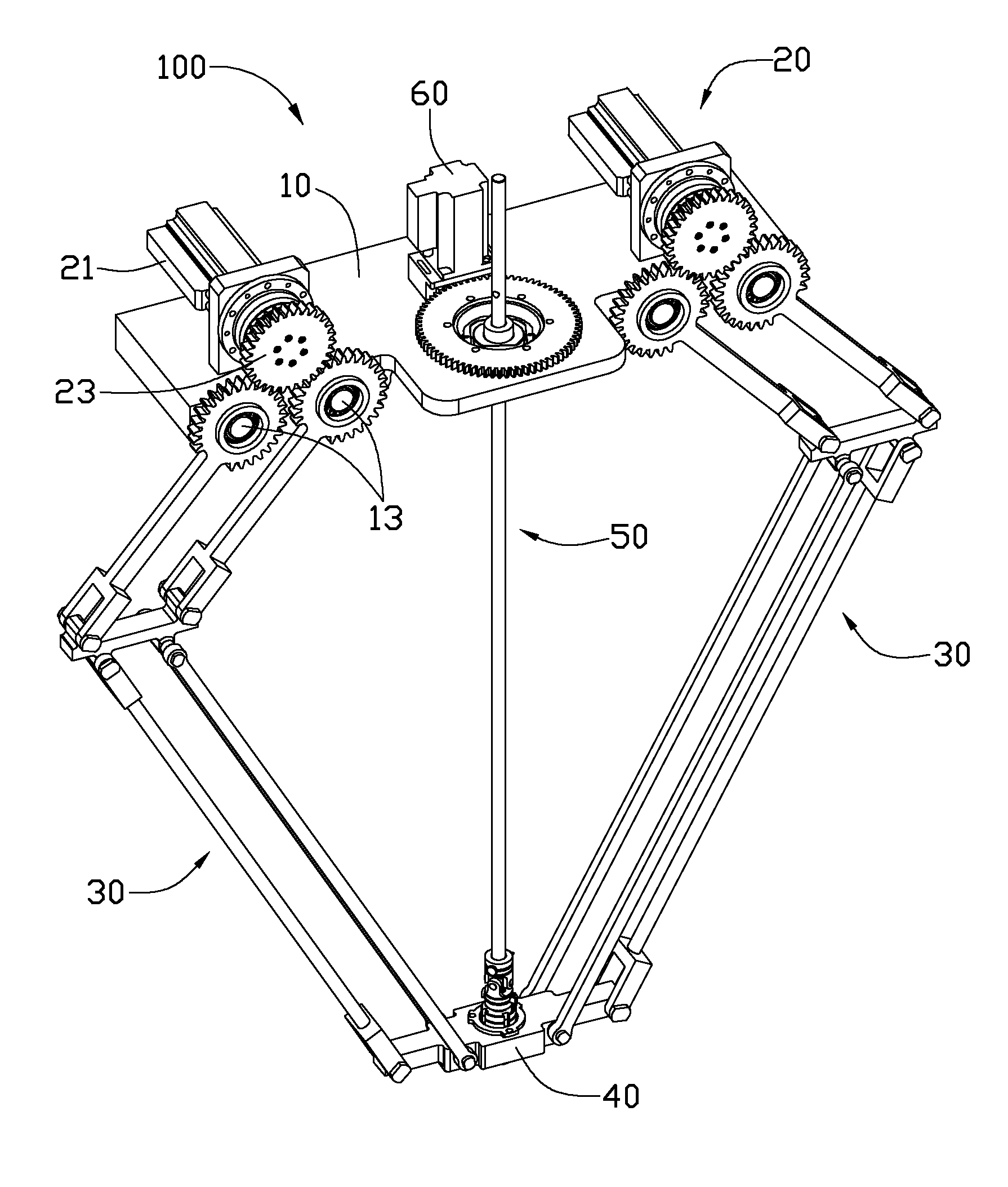
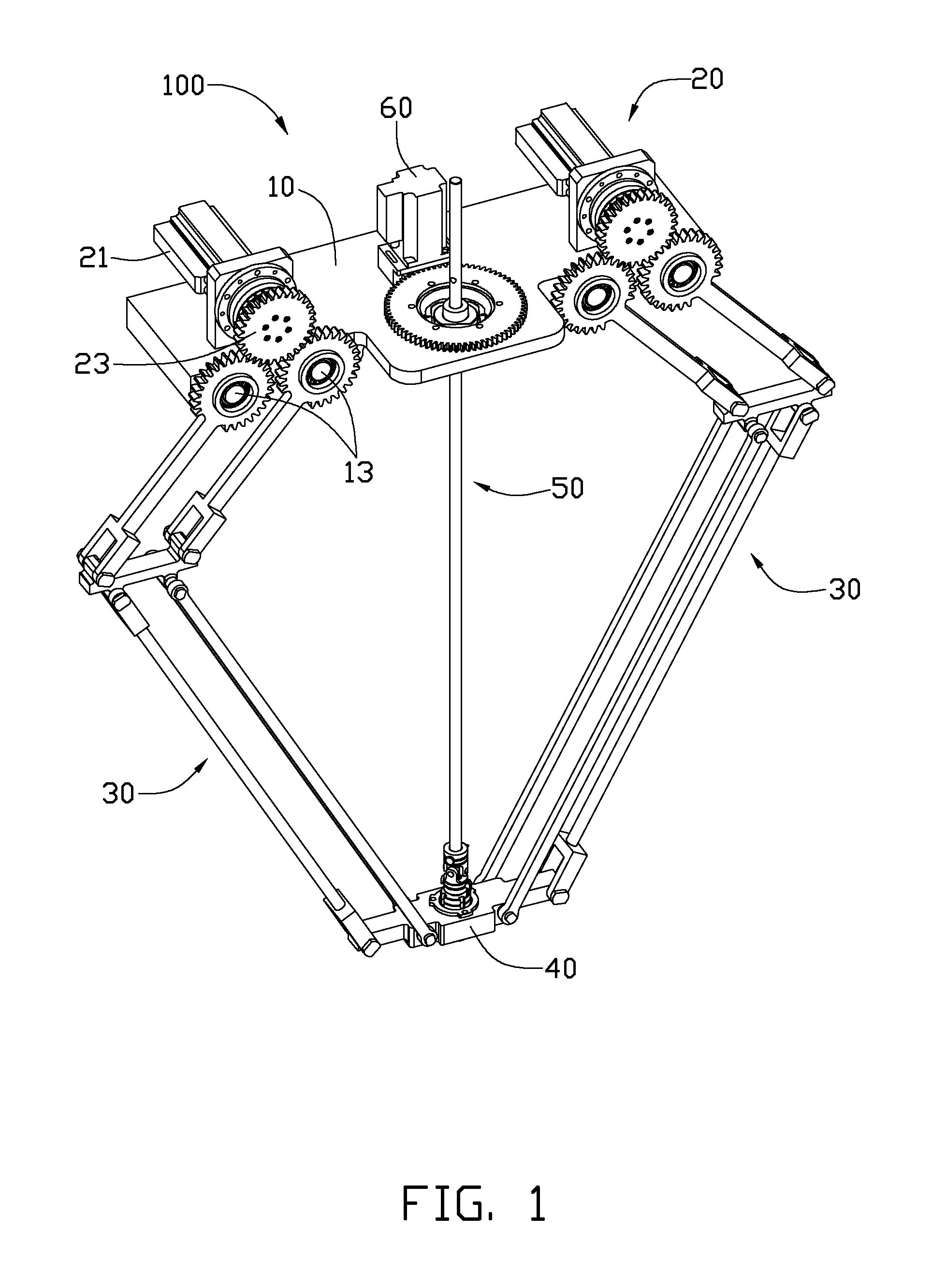
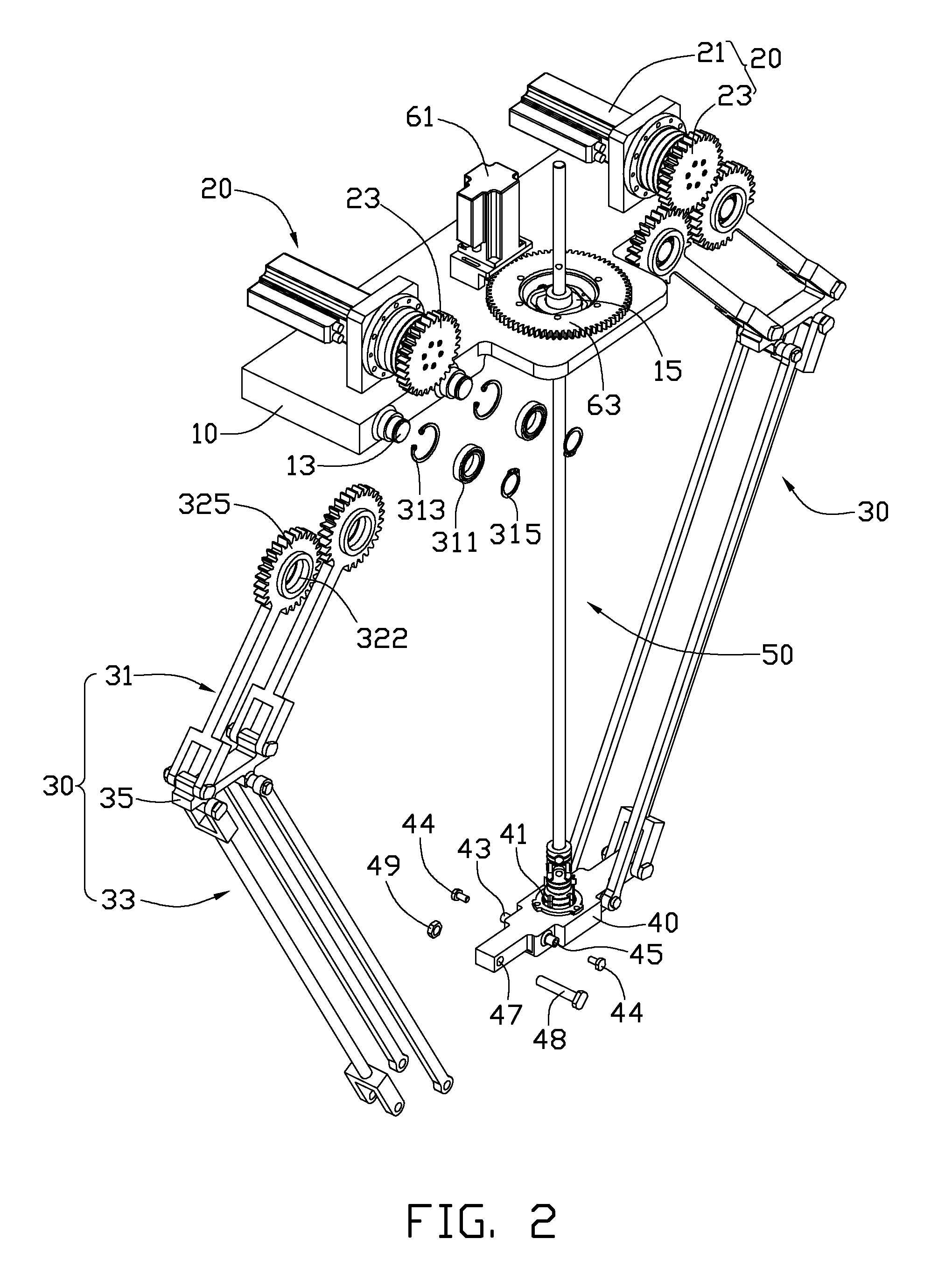
[0012]Referring to FIGS. 1 and 2, an embodiment of a parallel robot 100 includes a base plate 10, two first actuators 20, a second actuator 60, a mobile platform 40, two kinematic chains 30 and a rotary linkage shaft 50. The two first actuators 20 and the second actuator 60 are located on the base plate 10. Each of the two kinematic chains 30 is rotatably connected to the corresponding first actuator 20. The rotary linkage shaft 50 is rotatably connected to the second actuator 60. The second actuator 60 rotates the rotary linkage shaft 50 relative to the base plate 10.

[0013]The base plate 10 is substantially rectangular and includes four rotary shafts 13. The four rotary shafts are arranged in pairs, and extend outwardly from a side surface of the base plate 10. The base plate 10 defines a circular mounting hole 15 in a middle portion thereof.

[0014]Each first actuator 20 includes a rotational motor 21 and a gear 23 rotatably connected to the rotational motor 21. Each first actuator ...


PUM


Abstract

A parallel robot includes a base plate, two first actuators located on the base plate, a mobile platform, and two kinematic chains respectively interconnecting the base plate and the mobile platform. Each kinematic chain includes a driving bar assembly and a driven bar assembly. The driving bar assembly is connected to one of two first actuators. The driving bar includes two substantially parallel first transmission bars. Each of the first transmission bars includes a rotating portion rotatably connected to the base plate. The driven bar assembly interconnects the driving bar assembly and the mobile platform. Each of the two first actuators rotates two rotating portions of the two first transmission bars in the same direction simultaneously.

Description

BACKGROUND[0001]1. Technical Field[0002]The present disclosure relates to robots and, particularly to a parallel robot.[0003]2. Description of Related Art[0004]Parallel robots with two or three degrees of freedom are well suited for simple tasks, such as packaging and assembly, and provide advantages over more complex series robots such as, for example, with six degrees of freedom, in reference to simplicity, price, and speed.[0005]A commonly used parallel robot includes a base plate, a mobile platform, and two kinematic chains operated by two actuators fixed to the base plate. Each kinematic chain is made up of two bars linked at their ends. Each kinematic chain interconnects the mobile platform and the base plate.[0006]However, often, the parallel robot has a relatively low motion stability substantially perpendicular to a movable plane of the kinematic chains.[0007]Therefore, there is room for improvement within the art.BRIEF DESCRIPTION OF THE DRAWINGS[0008]The components in the...

Claims


Application Information

Patent Timeline
Patent Type & Authority Applications(United States)
IPC IPC(8): B25J18/00
CPCB25J9/107Y10T74/20317Y10T74/20305
Inventor ZHANG, GUO-QINGZHAO, ZHI-MING
Owner SHENZHENSHI YUZHAN PRECISION TECH CO LTD
Why Eureka
Try Eureka