
Wireless power feeder, wireless power receiver, and wireless power transmission system
a technology of wireless power transmission system and feeder, applied in the direction of electric variable regulation, process and machine control, instruments, etc., can solve the problem of not being able to feed big electric power, and achieve the effect of effective control of transmission power
- Summary
- Abstract
- Description
- Claims
- Application Information
AI Technical Summary
Benefits of technology
Problems solved by technology
Method used
Image

Examples
first embodiment
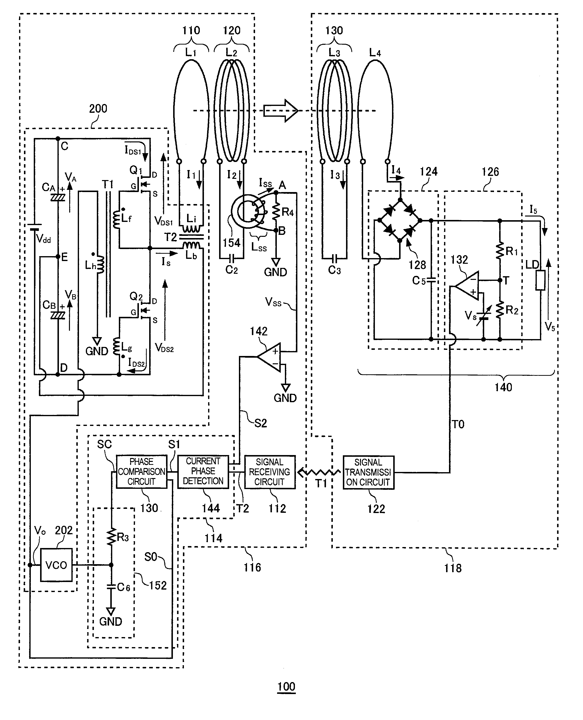
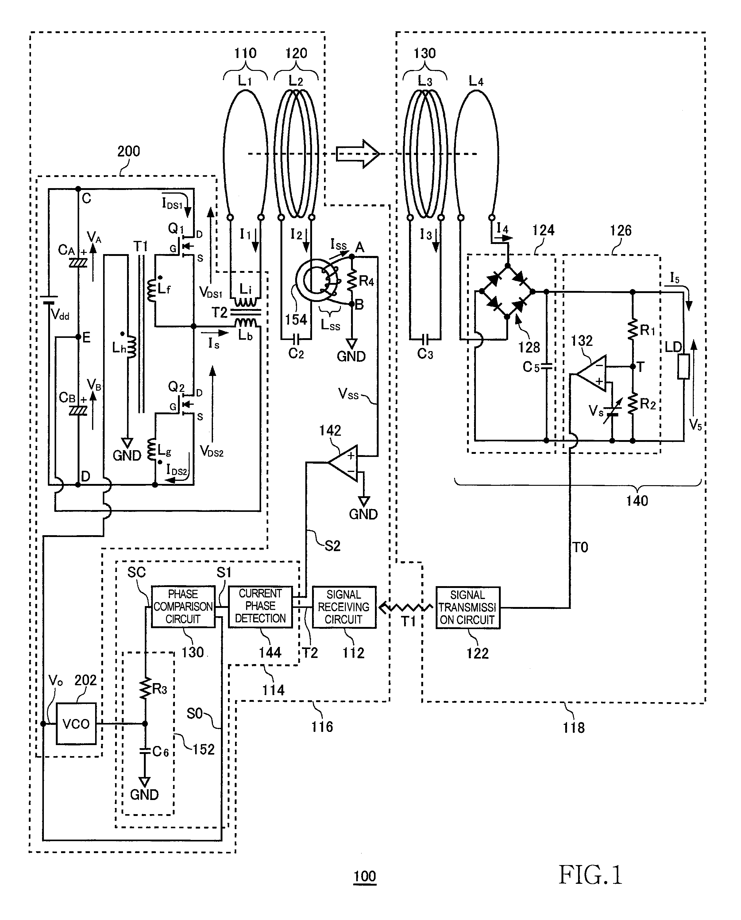
[0069]FIG. 1 is a system configuration view of a wireless power transmission system 100 according to the first embodiment. The wireless power transmission system 100 includes a wireless power feeder 116 and a wireless power receiver 118. The wireless power feeder 116 includes, as basic components, a power transmission control circuit 200, an exciting circuit 110, a feeding coil circuit 120, a phase detection circuit 114, and a signal receiving circuit 112. The wireless power receiver 118 includes a receiving coil circuit 130, a loading circuit 140, and a signal transmission circuit 122.
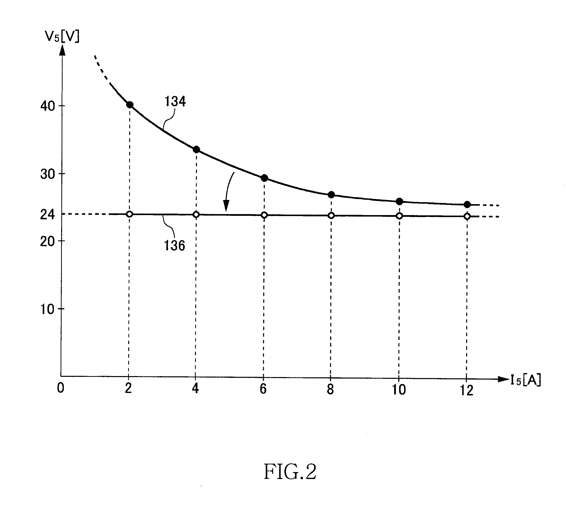
[0070]A distance (hereinafter, referred to as “inter-coil distance”) of about 0.2 m to 1.0 m is provided between a feeding coil L2 of the feeding coil circuit 120 and a receiving coil L3 of the receiving coil circuit 130. The wireless power transmission system 100 mainly aims to feed power from the feeding coil L2 to receiving coil L3 by wireless. In the first embodiment, a description will be made as...
second embodiment
[0133]FIG. 14 is a system configuration view of a wireless power transmission system 1100 according to the second embodiment. The wireless power transmission system 1100 includes a wireless power feeder 1116 and a wireless power receiver 1118. The wireless power feeder 1116 includes, as basic components, a power transmission control circuit 1200, an exciting circuit 1110, a feeding coil circuit 1120, a phase detection circuit 1114, and a signal receiving circuit 1112. The wireless power receiver 1118 includes a receiving coil circuit 1130, a loading circuit 1140, a control signal generation circuit 1170, a reference signal generation circuit 1172, and a signal transmission circuit 1122.
[0134]A distance (hereinafter, referred to as “inter-coil distance”) of about 0.2 m to 1.0 m is provided between a feeding coil L2 of the feeding coil circuit 1120 and a receiving coil L3 of the receiving coil circuit 1130. The wireless power transmission system 1100 mainly aims to feed power from the...
PUM
 Abstract
Description
Claims
Application Information