
Optical transmission module, electronic instrument, method for assembling optical transmission module, and optical transmission method
a technology of optical transmission module and optical transmission module, which is applied in the field of optical transmission module, electronic instrument, method for assembling optical transmission module, optical transmission method, etc., can solve the problems of insufficient low profile, low profile of electronic instrument, and difficult to establish a balance between bending property and transmission characteristic for data transmission. , to achieve the effect of low profil
- Summary
- Abstract
- Description
- Claims
- Application Information
AI Technical Summary
Benefits of technology
Problems solved by technology
Method used
Image

Examples
modification 1
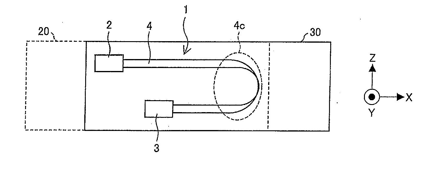
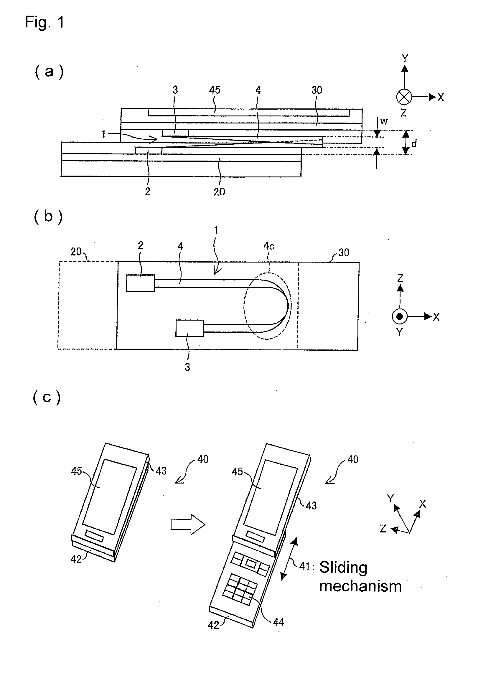
[0154]A modification of the configuration of the optical transmission module 1 according to one or more embodiments of the present invention illustrated in FIGS. 1(a) and 1(b) will be described below. FIG. 13 is a side view illustrating a configuration of an optical transmission module 1 according to Modification 1.
[0155]As illustrated in FIG. 13, in the optical transmission module 1 of Modification 1, a protective film 5 that protects the optical transmission path 4 is provided in one of a plurality of surfaces parallel to the optical transmission direction in the optical transmission path 4, as a member different from the member constituting the optical transmission path 4. The protective film 5 is a board film made of a material different from that of the member (optical transmission path 4) in which the optical signal is transmitted, and the fracture caused by the tension and wear-out of the optical transmission path 4 can be prevented by the protective film 5. In the plurality ...
modification 2
[0162]Another modification of the configuration of the optical transmission module 1 according to one or more embodiments of the present invention illustrated in FIGS. 1(a) and 1(b) will be described below. FIGS. 16(a) to 16(c) illustrate a configuration of an optical transmission module 1 according to Modification 2, wherein FIG. 16(a) is a top plan view, FIG. 16(b) is a side view, and FIG. 16(c) is an exploded perspective view. The optical transmission module 1 of Modification 2 is mounted while integrated with electric wiring (electric transmission path) 6.
[0163]As illustrated in FIGS. 16(a) to 16(c), the optical transmission module 1 of Modification 2 includes the electric wiring 6 in which the electric signal is transmitted between the transmission-side board 20 and the reception-side board 30. The optical transmission unit 2 and the optical reception unit 3 are mounted on the same surface in the electric wiring 6. The optical transmission path 4 is mounted on the optical trans...
modification 3
[0172]Still another modification of the configuration of the optical transmission module 1 according to one or more embodiments of the present invention illustrated in FIGS. 1(a) and 1(b) will be described below. FIG. 17 is a top plan view illustrating a configuration of an optical transmission module 1 according to Modification 3.
[0173]As illustrated in FIG. 17, the optical transmission module 1 of Modification 3 includes a guide unit 7 that guides the bending of the optical transmission path 4. The guide unit 7 is provided in one of the board surfaces of the transmission-side board 20 and the reception-side board 30. The guide unit 7 is disposed so as to extend in the direction vertical to the board surface. Therefore, the bending portion 4C of the optical transmission path 4 can be provided at the fixed position, and the bending of the optical transmission path 4 can stably be maintained.
PUM
 Abstract
Description
Claims
Application Information