Liquid ejecting head and liquid ejecting apparatus

a liquid ejecting head and liquid ejecting technology, which is applied in printing and other directions, can solve the problems of easy breakage of piezoelectric elements, inability to eject liquids from the liquid ejecting head, and difficulty in breaking piezoelectric elements compared to the opposite side of the extending section, so as to improve reliability and durability.

Active Publication Date: 2011-06-23
SEIKO EPSON CORP
View PDF6 Cites 7 Cited by
  • Summary
  • Abstract
  • Description
  • Claims
  • Application Information

AI Technical Summary

Benefits of technology

[0009]An advantage of some aspects of the invention is that it provides a liquid ejecting head and a liquid ejecting apparatus capable of preventing piezoelectric elements from being broken.

Problems solved by technology

There is a problem in that piezoelectric elements, which are used in such an ink jet type recording head, are easily broken due to the external environment, such as humidity or the like.
The above-described problem is present not only in the ink jet type recording head but also in the liquid ejecting head ejecting liquids other than ink.
Accordingly, in the extending section of the boundary between the active section and the inactive section of the piezoelectric element, the stiffness is not rapidly changed by the extending section so that breakage of the piezoelectric element is more difficult compared to the opposite side of the extending section.

Method used


Image

  • Liquid ejecting head and liquid ejecting apparatus
  • Liquid ejecting head and liquid ejecting apparatus
  • Liquid ejecting head and liquid ejecting apparatus

Examples


first embodiment

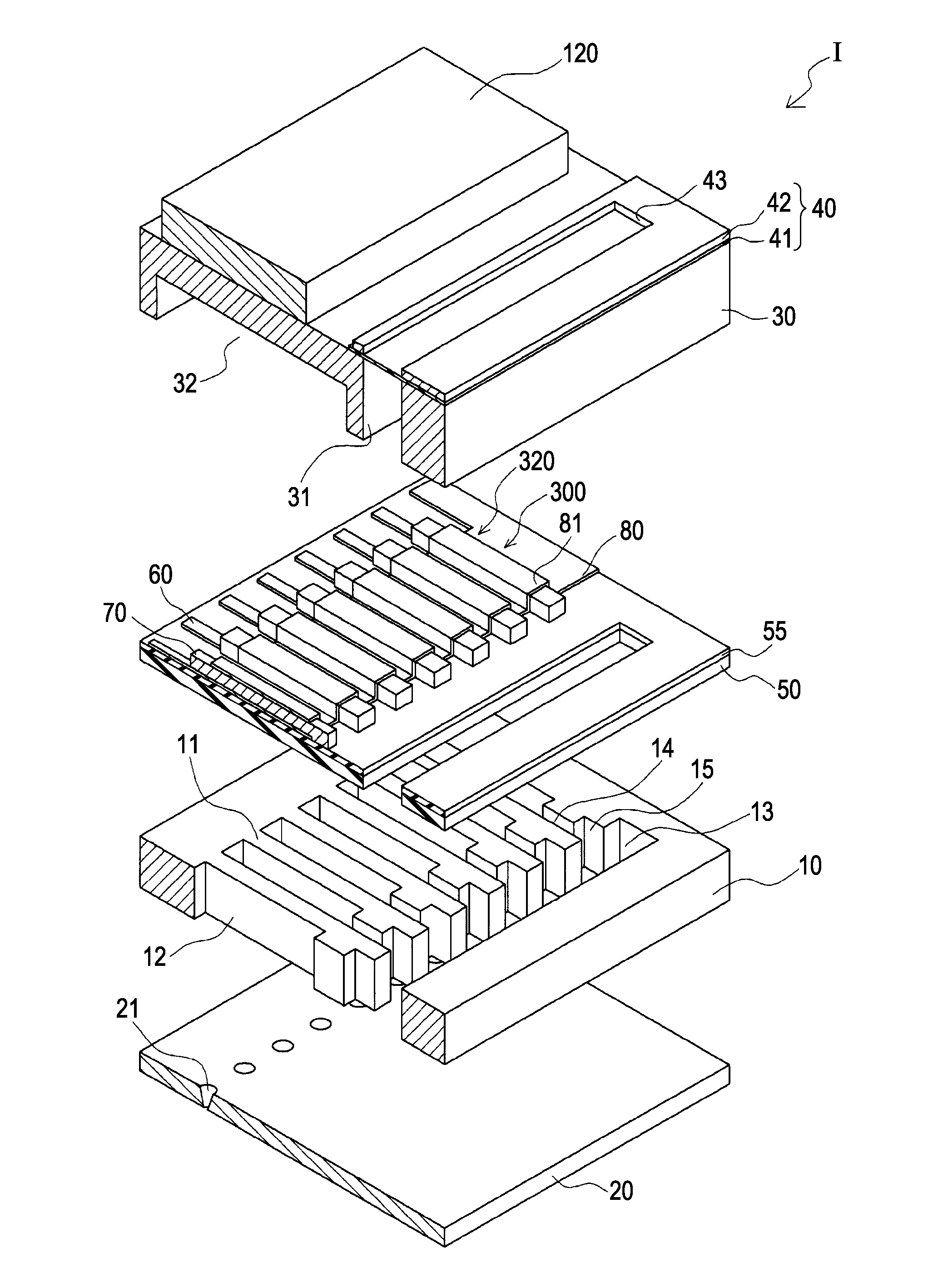
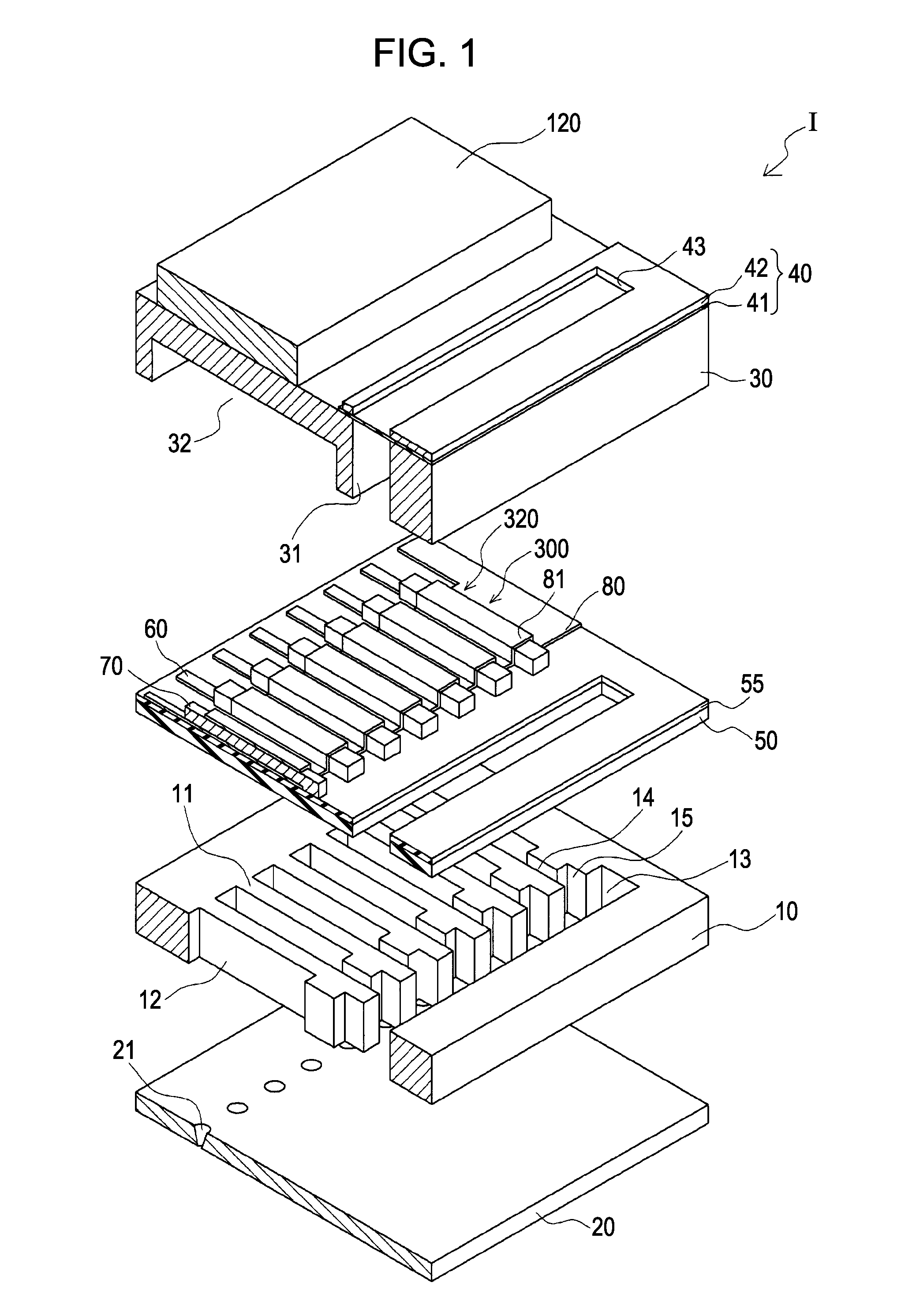
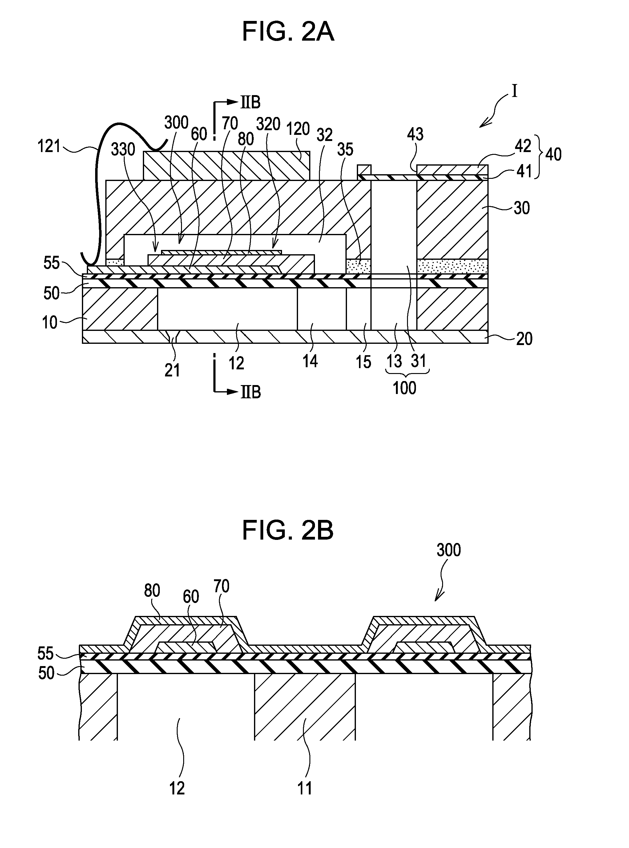
[0034]FIG. 1 is an exploded perspective view of an ink jet type recording head, that is an example of a liquid ejecting head according to a first embodiment of the invention, FIG. 2A is a sectional view of the ink jet type recording head and FIG. 2B is a sectional view taken along the line IIB-IIB of FIG. 2A.

[0035]As shown in drawings, in this embodiment, a flow channel forming substrate 10 is made of a silicon monocrystal substrate, and an elastic film 50 made of silicon dioxide is formed on one surface thereof.

[0036]In the flow channel forming substrate 10, a plurality of pressure generation chambers 12 are arranged in parallel in a width direction thereof. Also, a linking section 13 is formed in an area outside in a longitudinal direction of the pressure generation chamber 12 of the flow channel forming substrate 10, and the linking section 13 and each of the plurality of pressure generation chambers 12 is linked through an ink supply channel 14 and a linking channel 15 which are...

second embodiment

[0074]FIG. 5 is an enlarged plan view showing main parts of an ink jet type recording head that is an example of the liquid ejecting head according to a second embodiment of the invention. Also, the constituent elements similar to those of the first embodiment are represented by similar reference numbers thereof, and the repetition of the description will be avoided.

[0075]As shown in FIG. 5, the piezoelectric element 300A of the second embodiment has a first electrode 60A, the piezoelectric layer 70 and the second electrode 80.

[0076]The first electrode 60A has a straight-line section 62 provided at the center, a taper section 61A that is provided in a boundary A of the ink supply channel 14 side between the active section 320 and an inactive section 330 such that the width of the taper section 61A is gradually decreased toward the boundary A from the active section 320. Thus, the taper section 61A of the first electrode 60A is provided further inside (the pressure generation chamber...

third embodiment

[0080]FIG. 6 is an enlarged plan view showing main parts of an ink jet type recording head that is an example of the liquid ejecting head according to a third embodiment of the invention. Also, the constituent elements similar to those of the first embodiment are represented by similar reference numbers thereof, and the repetition of the description will be avoided.

[0081]As shown in FIG. 6, a piezoelectric element 300B of the third embodiment has a first electrode 60B, the piezoelectric layer 70 and the second electrode 80.

[0082]The first electrode 60B of the third embodiment is arranged so as to be at further outside than the end portion of the second electrode 80 of the pressure generation chamber 12 in the longitudinal direction. Thus, the end portion of the active section 320 in the longitudinal direction (the longitudinal direction of the pressure generation chamber 12) is defined by the end portion of the second electrode 80.

[0083]The first electrode 60B has the straight-line ...


PUM


Abstract

A liquid ejecting head includes a flow channel forming substrate having pressure generation chambers communicating with a nozzle opening and arranged in parallel along a lateral direction. A piezoelectric element is provided on one surface of the flow channel forming substrate in correspondence to the pressure generation chamber, and has a first electrode, a piezoelectric layer provided on the first electrode and a second electrode provided on the piezoelectric layer. In a direction intersecting with the arrangement direction of the pressure generation chambers, in boundaries between an active section that is a substantial driving section and an inactive section that is not a substantial driving section of the piezoelectric layer, the first electrode includes a taper section of which a width is gradually decreased toward the boundary from the active section side.

Description

CROSS-REFERENCE TO RELATED APPLICATIONS[0001]This application claims the benefit of priority to Japanese Patent Application No. 2009-289790 filed Dec. 21, 2009, the contents of which are hereby incorporated by reference in their entirety.BACKGROUND[0002]1. Technical Field[0003]The present invention relates to a liquid ejecting head and a liquid ejecting apparatus including a piezoelectric element.[0004]2. Related Art[0005]As a liquid ejecting head, here is an ink jet type recording head provided with piezoelectric elements that includes a first electrode, a piezoelectric layer and a second electrode on one surface of the flow channel forming substrate in which a pressure generation chamber linking with a nozzle opening is provided. The ink jet type recording head generates pressure change in the pressure generation chamber by means of a driving force of the piezoelectric elements so that ink droplets are ejected from the nozzle opening. There is a problem in that piezoelectric eleme...

Claims


Application Information

Patent Timeline
Patent Type & Authority Applications(United States)
IPC IPC(8): B41J2/045
CPCB41J2/055B41J2/14233B41J2/045B41J2002/14419B41J2002/14491B41J2002/14241
Inventor MIYAZAWA, HIROMUITO, HIROSHIKATO, JIROHIRAI, EIJUSHIMIZU, TOSHIHIRO
Owner SEIKO EPSON CORP
Why Eureka
Try Eureka