Liquid jet head and a liquid jet apparatus

a liquid jet and apparatus technology, applied in printing and other directions, can solve the problems of liable breakage of the piezoelectric elements used in the ink jet type recording head, and achieve the effects of preventing improving the durability of the vibrating plate, and improving the piezoelectric material layer

Active Publication Date: 2009-11-19
SEIKO EPSON CORP
View PDF2 Cites 70 Cited by
  • Summary
  • Abstract
  • Description
  • Claims
  • Application Information

AI Technical Summary

Benefits of technology

[0005]An advantage of some aspects of the invention is that it provides a liquid jet head capable of preventing piezoelectric elements from being broken, and a liquid jet apparatus.
[0007]In this aspect, the surface of the piezoelectric material layer opposite each of the pressure generation chamber is substantially covered with an upper electrode film. Therefore, the piezoelectric material layer can be prevented from being broken due to moisture in the atmosphere. In addition, if the relationship between the distance D1 and the distance D2 is satisfied, a sufficient interval between the lower electrode and the upper electrode constituting each piezoelectric element is secured. If an interval between the lower electrode and the upper electrode is secured such that the relationship is satisfied, insulation breakdown between the lower electrode and the upper electrode can be reliably suppressed.
[0008]The lower electrode may be provided independently to correspond to each of the pressure generation chambers so as to form an individual electrode of the piezoelectric element, and the upper electrode may be provided to successively extend in the arrangement direction of the pressure generation chambers so as to form a common electrode of a plurality of the piezoelectric elements. The lower electrode may form a common electrode of the piezoelectric elements, and the upper electrode may be divided by a partition wall between the pressure generation chambers so as to form an individual electrode of the piezoelectric element. With this configuration, the piezoelectric material layer can be reliably prevented from being broken, regardless of the electrode structure of the piezoelectric element.
[0009]One end portion of the lower electrode in a longitudinal direction of the pressure generation chamber may be located within a region opposite the corresponding pressure generation chamber, an end portion of the upper electrode in the longitudinal direction of each of the pressure generation chambers may be located within a region opposite the corresponding pressure generation chamber, and a substantial driving portion of the piezoelectric element is provided between the end portion of the lower electrode and the end portion of the upper electrode. With this configuration, there is no case in which a vibrating plate near both end portions in the longitudinal direction of the pressure generation chamber is deformed when the piezoelectric element is driven, and as a result, durability of the vibrating plate is improved.
[0010]A protective film made of a moisture-resistant material may be provided to cover an edge portion of the upper electrode and an exposed surface of the piezoelectric material layer in a region opposite to each of the pressure generation chambers. With this configuration, the piezoelectric material layer can be reliably prevented from being broken due to moisture in the atmosphere.
[0011]According to another aspect of the invention, a liquid jet apparatus includes the above-described liquid jet head. In this aspect, a reliable liquid jet apparatus that includes a head having improved durability can be realized.

Problems solved by technology

The piezoelectric elements, which are used in such an ink jet type recording head, are liable to be broken due to external environment, such as humidity or the like.

Method used


Image

  • Liquid jet head and a liquid jet apparatus
  • Liquid jet head and a liquid jet apparatus
  • Liquid jet head and a liquid jet apparatus

Examples


first embodiment

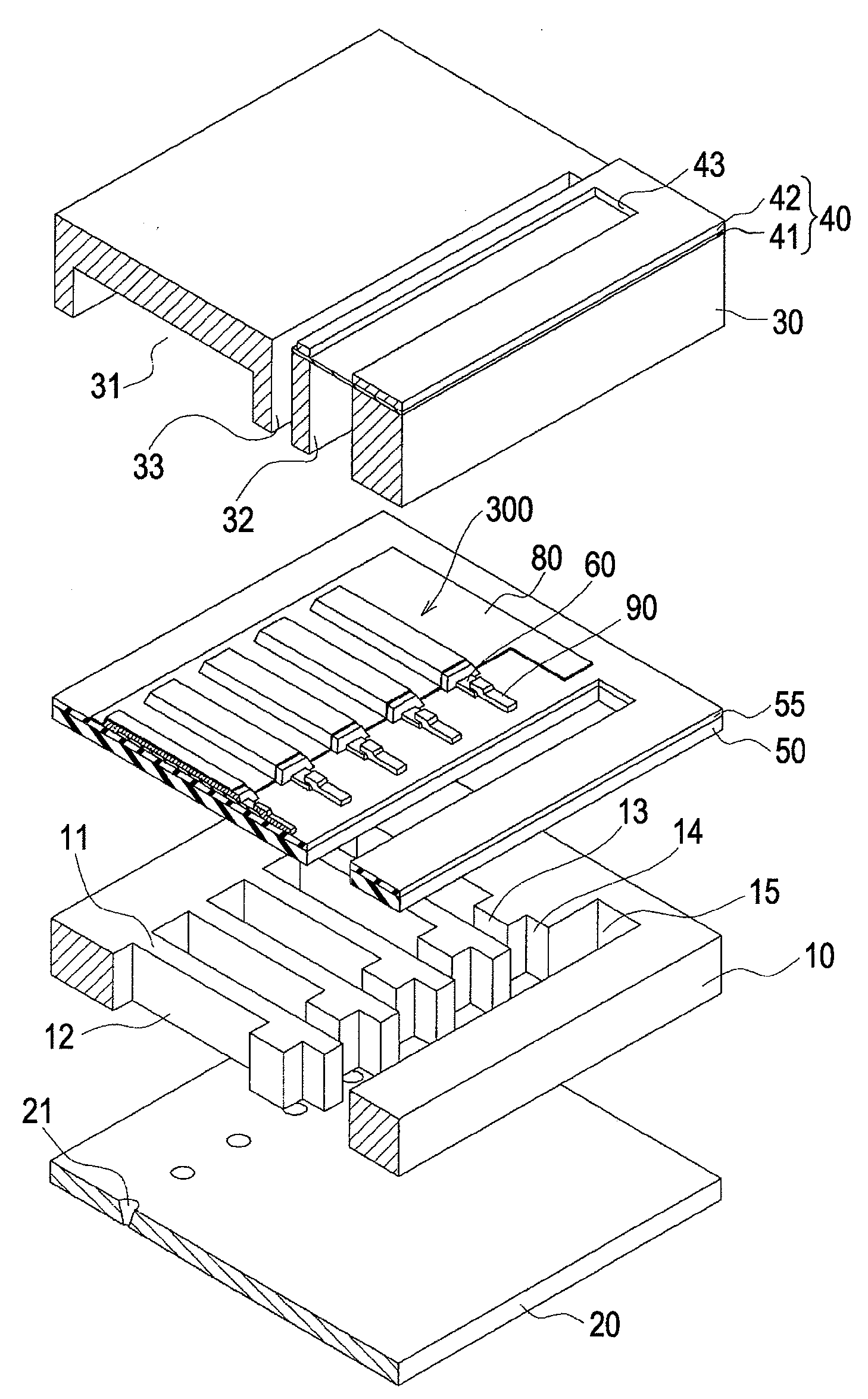
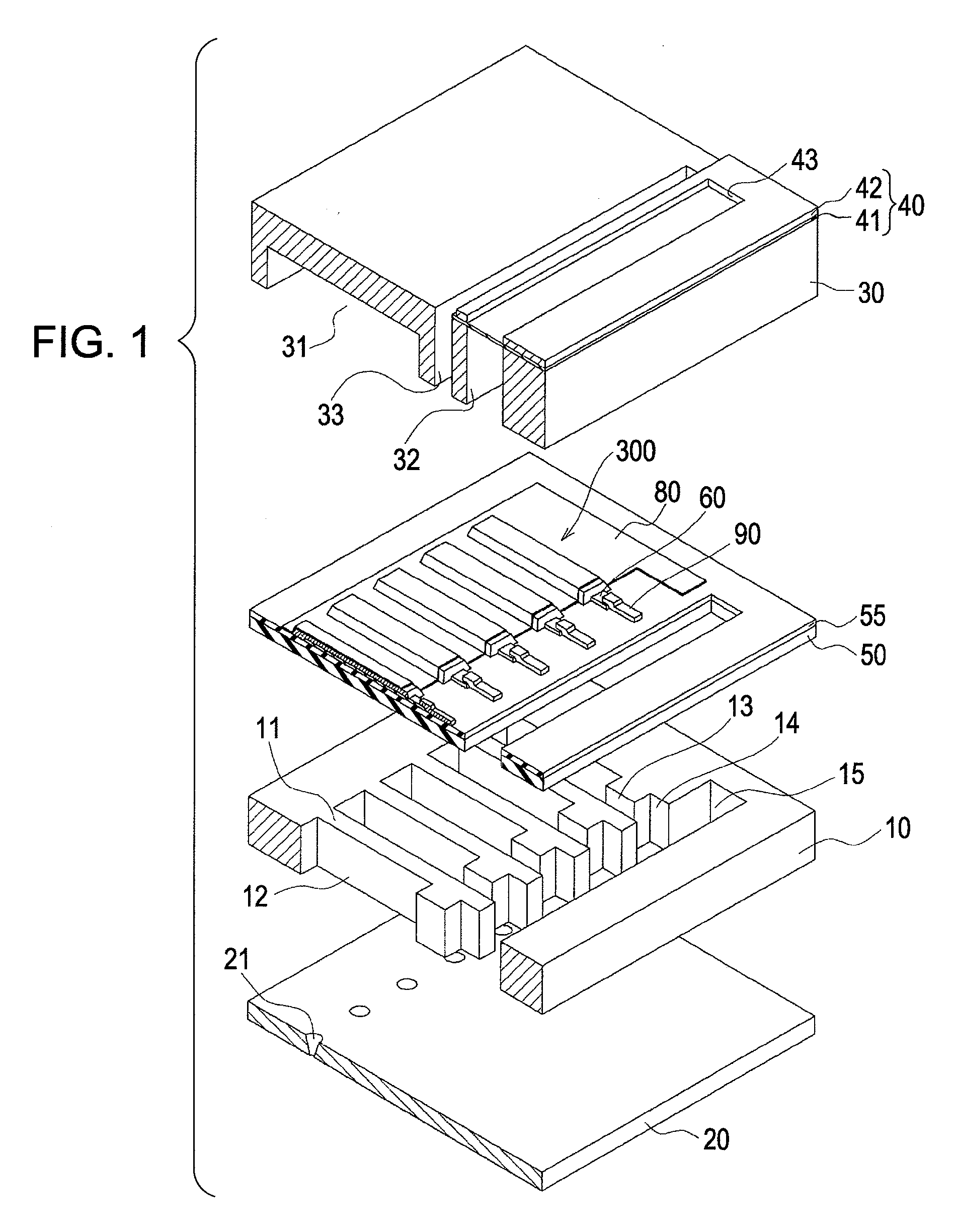
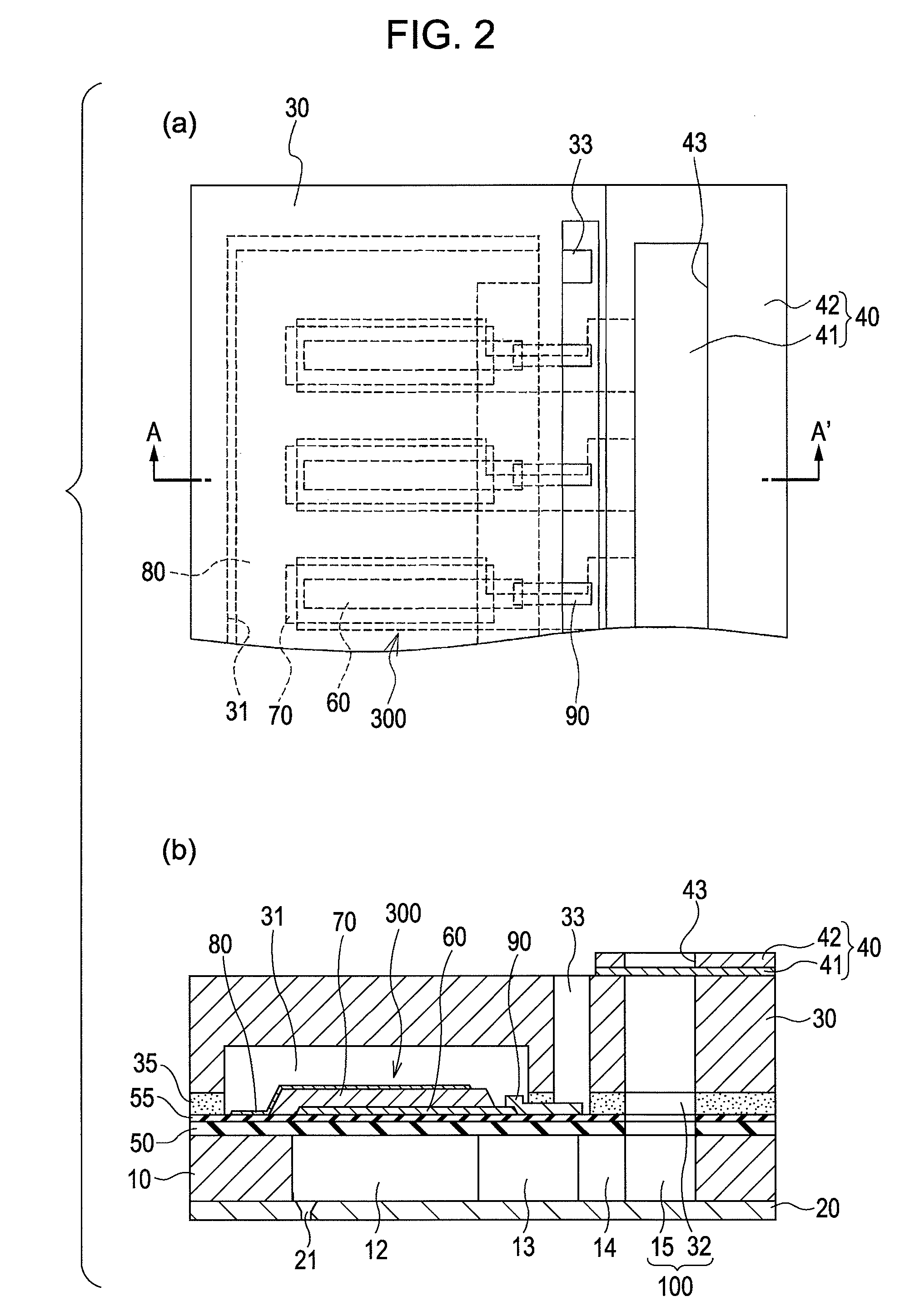
[0038]FIG. 1 is an exploded perspective view showing the schematic configuration of an ink jet type recording head, which is an example of a liquid jet head, according to a first embodiment of the invention. FIG. 2 is a plan view of FIG. 1 and a sectional view taken along the line A-A′ of FIG. 1.

[0039]As shown in the drawings, in this embodiment, a flow channel forming plate 10 is made of a silicon monocrystal plate having a crystal surface direction (110), and an elastic film 50 made of an oxide film is formed on one surface of the flow channel forming plate 10. In the flow channel forming plate 10, a plurality of pressure generation chambers 12 that are partitioned by a partition wall 11 are arranged in a width direction of the flow channel forming plate 10. The elastic film 50 forms one surface of each of a plurality of pressure generation chambers 12.

[0040]The flow channel forming plate 10 is provided with an ink supply channel 13 and a communicating channel 14, which are partit...

second embodiment

[0057]FIG. 5 is a sectional view showing the configuration of a piezoelectric element according to a second embodiment of the invention. As shown in FIG. 5, in this embodiment, the piezoelectric material layer 70 is formed successively to extend over a plurality of pressure generation chambers 12 arranged. That is, the second embodiment is the same as the first embodiment, except that a piezoelectric material layer 71 remains between the arranged piezoelectric elements 300 to have a thickness smaller than that of the piezoelectric material layer 70 constituting the piezoelectric elements 300. The thickness of the piezoelectric material layer 71 is not particularly limited, and may be appropriately set depending on the displacement of each of the piezoelectric elements 300.

[0058]In this way, if the piezoelectric material layer 70 is provided successively, the vibrating plate, that is, the elastic film 50 and the insulator film 55 can be prevented from being broken when the piezoelect...

third embodiment

[0060]FIG. 6 is an exploded perspective view showing the schematic configuration of an ink jet type recording head according to a third embodiment of the invention. FIG. 7 is a plan view of FIG. 6, and a sectional view taken along the line C-C′ of FIG. 6. FIG. 8 is a sectional view showing the configuration of a piezoelectric element according to the third embodiment of the invention. The same members as the members shown in FIGS. 1 to 3 are represented by the same reference numerals, and descriptions thereof will be omitted.

[0061]This embodiment is the same as the first embodiment, except that lower electrode films 60 constituting the piezoelectric elements 300 forms a common electrode film of the piezoelectric elements 300, and upper electrode films 80 form individual electrodes.

[0062]As shown in the drawings, the lower electrode film 60 of this embodiment extends from one end portion in the longitudinal direction of each of the pressure generation chambers 12 to the peripheral wa...


PUM


Abstract

A lower electrode 60 in a region opposite each of pressure generation chambers 12 is formed to have a width smaller than the width of the corresponding pressure generation chamber 12, and an upper surface and an end surface of the lower electrode 60 in a region corresponding to each of the pressure generation chambers 12 is covered with a piezoelectric material layer 70. An end surface of the piezoelectric material layer 70 forms a slope surface sloping downward toward the outside, an upper surface and an end surface of the piezoelectric material layer 70 in the region opposite each of the pressure generation chambers 12 are covered with an upper electrode 80, and a distance D1 between the upper surface of the lower electrode 60 and the upper surface of the piezoelectric material layer 70 and a distance D2 between the end surface of the lower electrode and the end surface of the piezoelectric material layer 70 satisfy the relationship D2≧D1.

Description

BACKGROUND OF THE INVENTION[0001]The entire disclosure of Japanese Patent Application No. 2008-014265, filed Jan. 24, 2008 is incorporated by reference herein.FIELD OF THE INVENTION[0002]The present invention relates to a liquid jet head that jets liquid droplets from nozzles by displacement of piezoelectric elements, and a liquid jet apparatus, and in particular, to an ink jet type recording head that jets ink droplets as liquid droplets, and an ink jet type recording apparatus.INVENTION OF RELATED ART[0003]An ink jet type recording head, which is an example of a liquid jet head jetting liquid droplets, includes a flow channel forming plate having pressure generation chambers, and piezoelectric elements provided on one surface of the flow channel forming plate, each of the piezoelectric elements having a lower electrode, a piezoelectric material layer, and an upper electrode. Pressure is given into the pressure generation chambers by displacement of the piezoelectric elements, and ...

Claims


Application Information

Patent Timeline
Patent Type & Authority Applications(United States)
IPC IPC(8): B41J2/045
CPCB41J2/055B41J2/14233B41J2/14209B41J2002/14419B41J2002/14241
Inventor YAZAKI, SHIRO
Owner SEIKO EPSON CORP
Why Eureka
Try Eureka