Fluid ejecting apparatus and fluid receiving method

a technology of fluid receiving and ejecting apparatus, which is applied in the direction of printing, etc., can solve the problems of inability to perform the flushing process, inability to print sheets, and inability to eject ink,

Active Publication Date: 2011-06-30
SEIKO EPSON CORP
View PDF8 Cites 0 Cited by
  • Summary
  • Abstract
  • Description
  • Claims
  • Application Information

AI Technical Summary

Benefits of technology

[0020]According to this configuration, it is possible to obtai...

Problems solved by technology

In the printer, if ink (fluid) is not ejected for some time from a specific nozzle during a printing process, the ink in the nozzle is thickened or solidified, dust becomes attached to the nozzle, or bubbles become mixed with the ink in the nozzle, which may cause an erroneous ejecting of the ink.
For this reason, the flushing process cannot be performed when the printing process is performed on an elongated sheet such as a continuous sheet.
Further, since the ink needs to be ejected to the absorbing member at a timing at which the absorbing member is disposed and transported between the printing sheets and faces the printing head, a problem ari...

Method used


Image

  • Fluid ejecting apparatus and fluid receiving method
  • Fluid ejecting apparatus and fluid receiving method
  • Fluid ejecting apparatus and fluid receiving method

Examples


Embodiment Construction

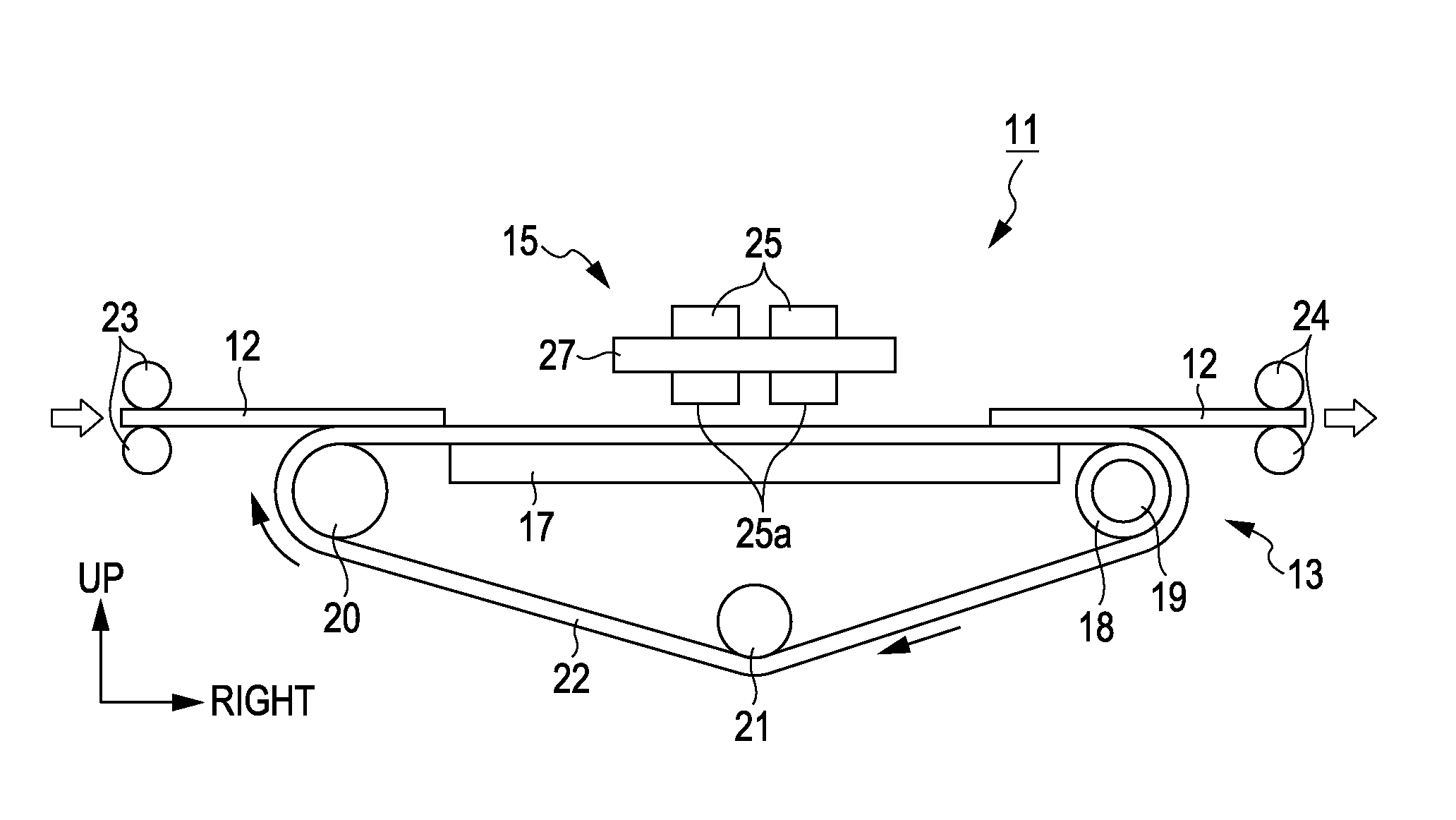
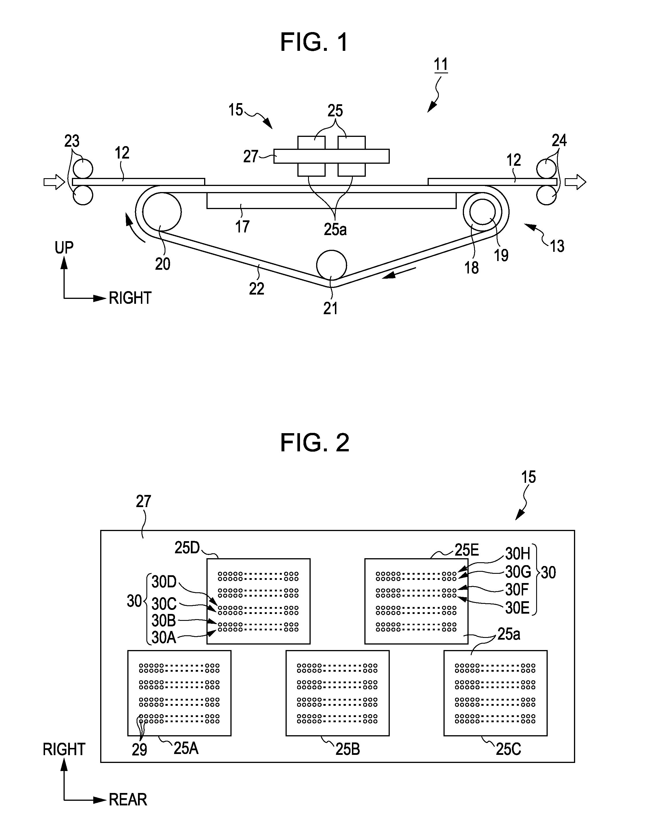
[0029]Hereinafter, an embodiment will be described with reference to the accompanying drawings, in which a fluid ejecting apparatus of the invention is embodied as an ink jet printer. Further, in the description below, the “longitudinal direction”, the “horizontal direction”, and the “vertical direction” respectively indicate the longitudinal direction, the horizontal direction, and the vertical direction depicted by the arrows in FIGS. 1 and 2.

[0030]As shown in FIG. 1, an ink jet printer (hereinafter, referred to as a “printer”) 11 as a fluid ejecting apparatus includes a transportation unit 13 which transports a printing sheet 12 and a printing head unit 15 which performs a printing process on the printing sheet 12.

[0031]The transportation unit 13 includes a platen 17 which is formed as an elongated rectangular plate shape in the horizontal direction. A driving roller 18 extending in the longitudinal direction is disposed on the right side of the platen 17 so as to be rotationally...


PUM


Abstract

Provided is a fluid ejecting apparatus including: a fluid ejecting head; a receiving member which is linear; a support member which supports the receiving member; a support member movement unit which moves the support member between a first position and a second position so that the receiving member is located at a receiving position capable of receiving the fluid ejected from the nozzles at the first position, and the receiving member is located at a retreat position deviating from the receiving position at the second position; and a tensile force changing unit which is capable of changing tensile force changing unit changes the tensile force applied to the receiving member from a first tensile force to a second tensile force smaller than the first tensile force when the support member movement unit moves the support member from the second position to the first position.

Description

BACKGROUND[0001]1. Technical Field[0002]The present invention relates to a fluid ejecting apparatus such as an ink jet printer and a fluid receiving method.[0003]2. Related Art[0004]In general, an ink jet printer (hereinafter, simply referred to as a “printer”) has been known as a fluid ejecting apparatus that ejects a fluid from a nozzle formed on a fluid ejecting head toward a target. In the printer, if ink (fluid) is not ejected for some time from a specific nozzle during a printing process, the ink in the nozzle is thickened or solidified, dust becomes attached to the nozzle, or bubbles become mixed with the ink in the nozzle, which may cause an erroneous ejecting of the ink. Therefore, generally, the printer performs a flushing process in which the ink is ejected from the nozzle on the basis of a control signal not involved with the printing process.[0005]That is, for example, in a serial type printer designed to perform a printing process while a printing head scans the primar...

Claims


Application Information

Patent Timeline
IPC IPC(8): B41J2/01
CPCB41J2/16526
Inventor KAWAKAMI, TAKAYUKI
Owner SEIKO EPSON CORP
Why Eureka
Try Eureka