
Support mechanism for portable electronic device

a technology for supporting mechanisms and electronic devices, applied in the direction of electric apparatus casings/cabinets/drawers, furniture parts, instruments, etc., can solve the problem of users having difficulty in viewing the display screen disposed on the housing

Inactive Publication Date: 2011-07-07
SHENZHEN FUTAIHONG PRECISION IND CO LTD +1
View PDF7 Cites 51 Cited by
  • Summary
  • Abstract
  • Description
  • Claims
  • Application Information

AI Technical Summary

Problems solved by technology

Therefore, when the portable electronic device is placed on a desk, it can be difficult for users to view a display screen disposed on the housing.

Method used


Image

  • Support mechanism for portable electronic device
  • Support mechanism for portable electronic device
  • Support mechanism for portable electronic device

Examples


Embodiment Construction

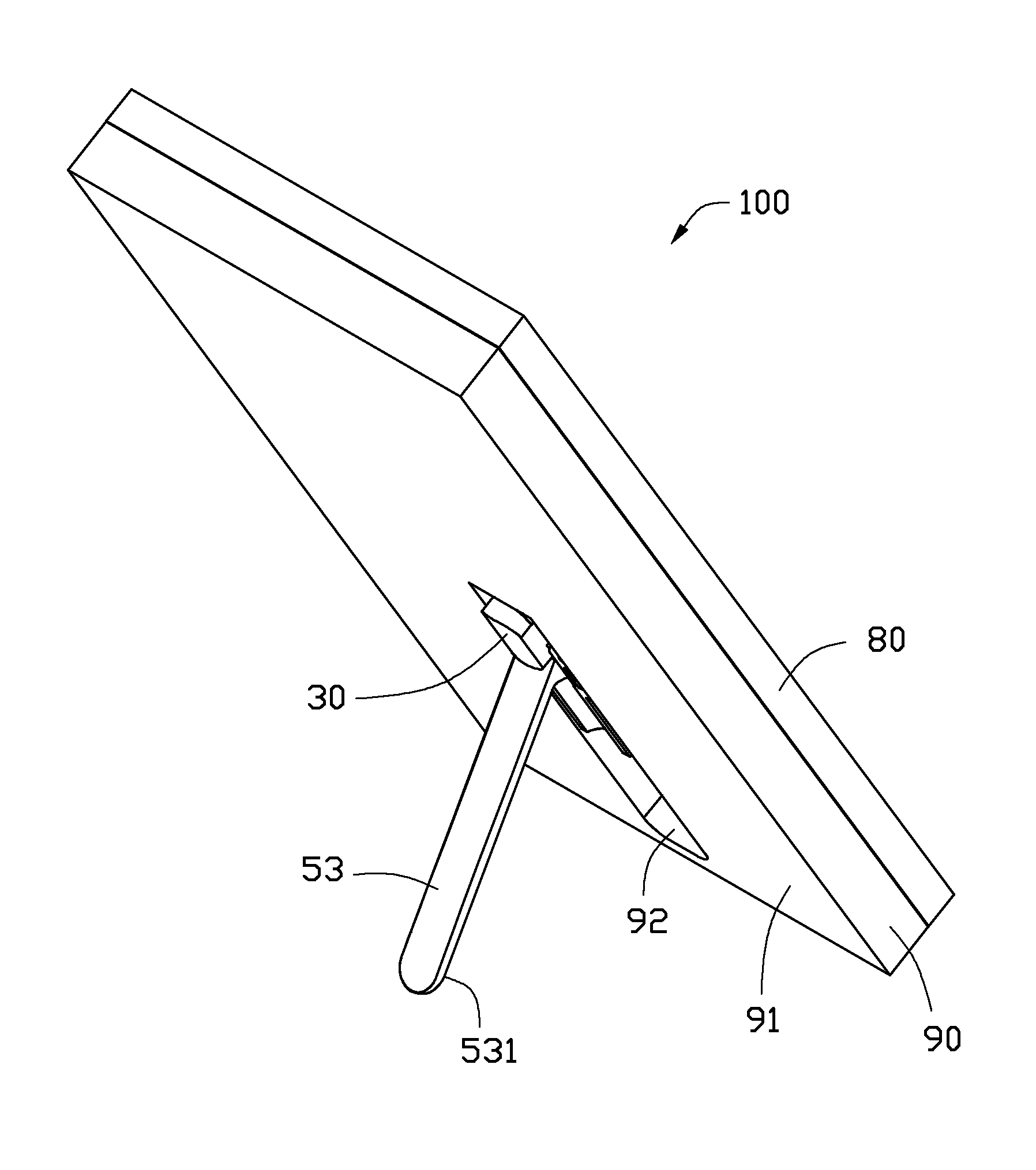
[0012]The disclosed support mechanism in accordance with various exemplary embodiments herein may be applied in portable electronic devices such as mobile phones, personal digital assistants (PDAs), and so on. In the exemplary embodiment, the support mechanism as used in a mobile phone is illustrated. However, the disclosure is not limited to use in a mobile phone.

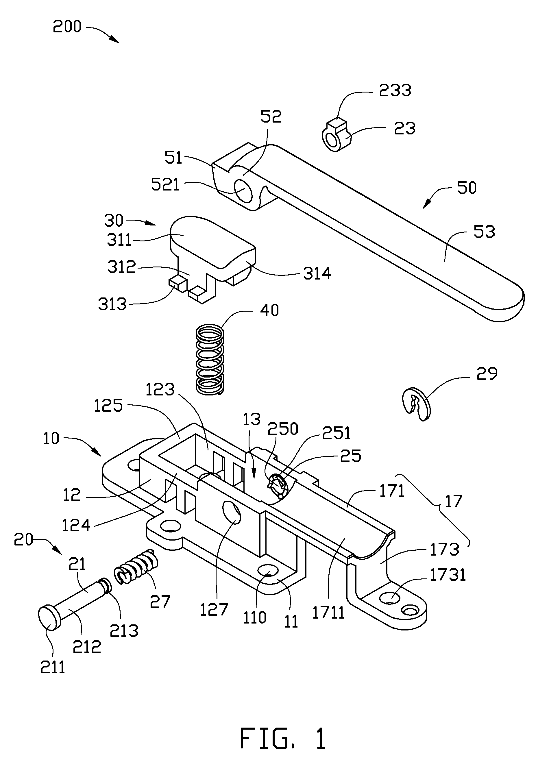
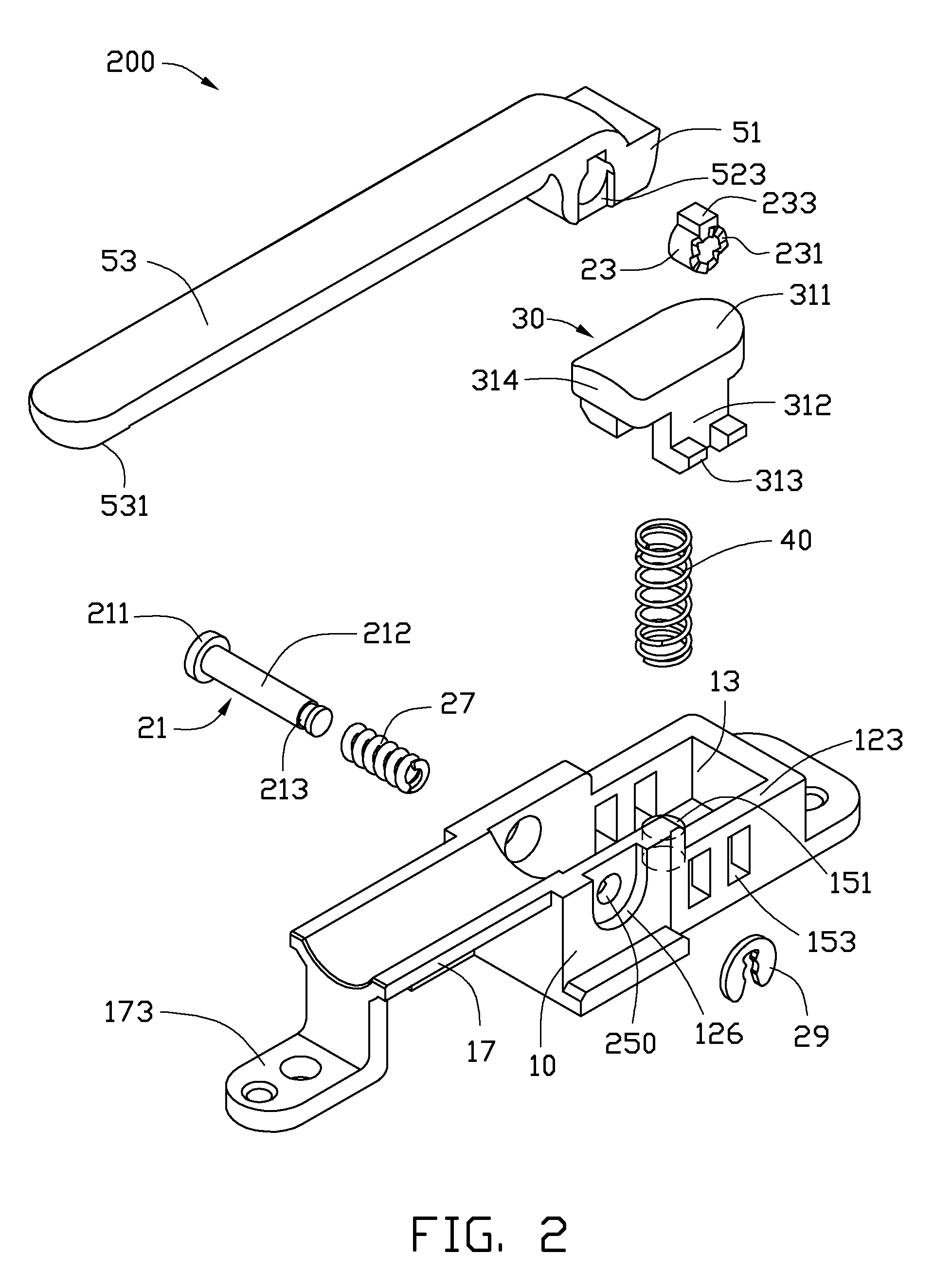
[0013]FIGS. 1 and 2 show a support mechanism 200 including a seat 10, a hinge assembly 20, a button 30, an elastic member 40, and a support member 50.

[0014]The seat 10 includes a base plate 11 defining a plurality of fastener holes 110. A frame 12 is positioned on the base plate 11. The frame 12 includes a first sidewall 123, a second sidewall 124 and two opposite end walls 125. The first, second sidewalls 123, 124 and the end walls 125 cooperatively surround a cavity 13. A follower 25 is integrally formed with the first sidewall 123. The follower 25 includes a central hole 250 and a cam surface 251. The cam surface 251 fa...


PUM


Abstract

An exemplary support mechanism for a portable electronic device includes a seat, a button, a support member, and a hinge assembly. The seat defines a cavity. The button is received in the cavity. The support member includes a knuckle portion. The knuckle portion is received in the cavity. The button abuts against the support member. The hinge assembly connects the knuckle portion to the seat. When the button is pressed to force the hinge assembly to unlock, the hinge assembly drives the support member to rotate.

Description

BACKGROUND[0001]1. Technical Field[0002]The present disclosure relates to support mechanisms, particularly to a support mechanism used in a portable electronic device.[0003]2. Description of Related Art[0004]Portable electronic devices such as mobile phones include several types of support systems such as bar type, flip-type and slide-type so as to satisfy different tastes of different people. Current support systems, typically only allow the electronic device to be held in a predetermined position. Therefore, when the portable electronic device is placed on a desk, it can be difficult for users to view a display screen disposed on the housing.[0005]Therefore, there is room for improvement within the art.BRIEF DESCRIPTION OF THE DRAWINGS[0006]Many aspects of the disclosed support mechanism can be better understood with reference to the following drawings. The components in the drawings are not necessarily drawn to scale, the emphasis instead being placed upon clearly illustrating th...

Claims


Application Information

Patent Timeline
Patent Type & Authority Applications(United States)
IPC IPC(8): H05K7/00F16M11/22
CPCH05K5/0234H04M1/04
Inventor DUAN, CHAOCHEN, CHIA-HUA
Owner SHENZHEN FUTAIHONG PRECISION IND CO LTD
Features
  • Generate Ideas
  • Intellectual Property
  • Life Sciences
  • Materials
  • Tech Scout
  • Unparalleled Data Quality
  • Higher Quality Content
  • 60% Fewer Hallucinations
Learn More