
Electronic device disposing structure

a technology of electronic devices and disposing structures, which is applied in the direction of electrical transducers, transducer types, piezoelectric/electrostrictive transducers, etc., can solve the problems of high cost, easy damage, and troublesome use of electronic devices

Inactive Publication Date: 2011-07-14
LIU KENG YUAN
View PDF2 Cites 47 Cited by
  • Summary
  • Abstract
  • Description
  • Claims
  • Application Information

AI Technical Summary

Benefits of technology

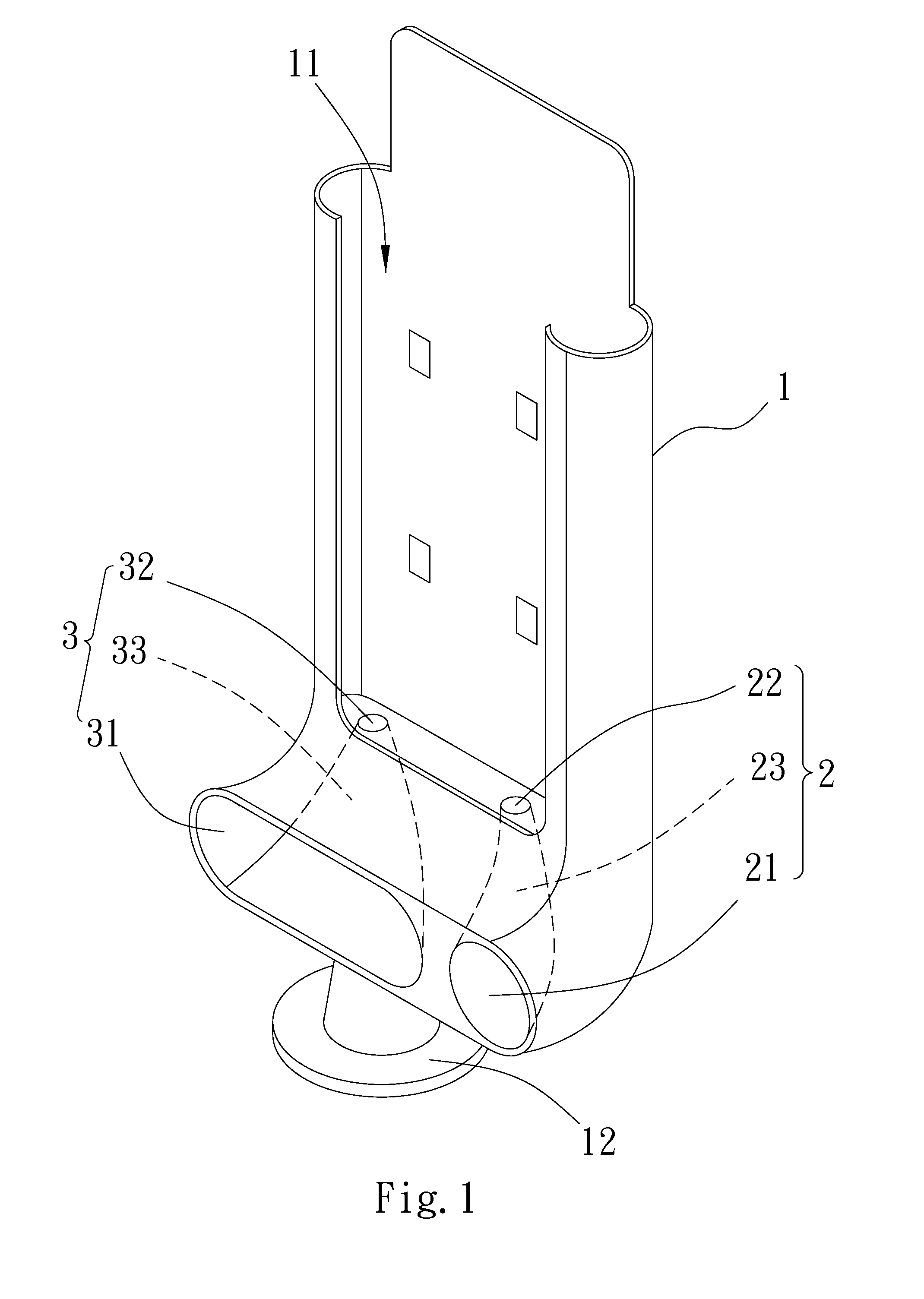
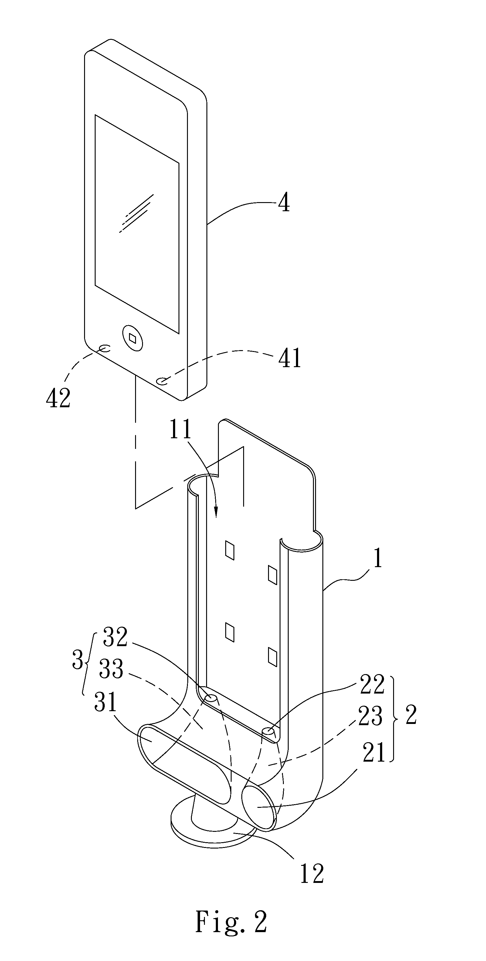
[0006]Therefore, it is a primary objective of the present invention to provide an electronic device disposing structure for combining a portable electronic device into a position limiting area of a stand, such that a sound receiving microphone and a sound emitting speaker of the portable electronic device correspond to a sound receiving channel and a sound emitting channel respectively to achieve a hand-free effect and a sound amplification without requiring a circuit design.
[0008]Therefore, the present invention provides an electronic device disposing structure capable of combining the portable electronic device into the position limiting area of the stand, such that a sound receiving microphone and a sound emitting speaker correspond to a sound receiving channel and a sound emitting channel respectively, so as to achieve a hand-free effect and a sound amplification without requiring a circuit design.

Problems solved by technology

However, the aforementioned simple disposing stand requires various different peripherals and causes tremendous troubles for using the electronic device.
Furthermore, the disposing stand combined with the connecting wires and the input / output functions not only comes with a complicated structure, but also requires the installation of related circuits that incurs a higher cost and results in a damage easily.

Method used


Image

  • Electronic device disposing structure
  • Electronic device disposing structure
  • Electronic device disposing structure

Examples


Embodiment Construction

[0014]To make it easier for the examiner to understand the objects, characteristics and effects of this invention, we use preferred embodiments together with the attached drawings for the detailed description of the invention as follows.

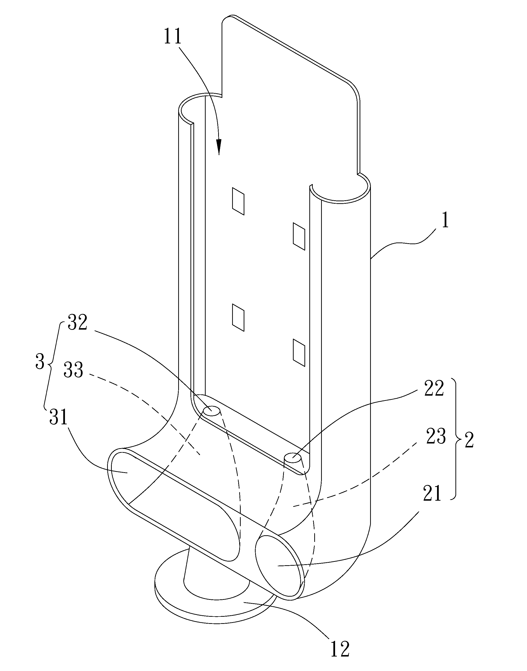
[0015]With reference to FIG. 1 for a perspective view of an electronic device disposing structure in accordance with a first preferred embodiment of the present invention, the electronic device disposing structure comprises a stand 1, a sound receiving channel 2 and a sound emitting channel 3.

[0016]The stand 1 has a position limiting area 11, and the stand 1 further includes a support unit 12 movably combined with the stand 1.

[0017]The sound receiving channel 2 is disposed on the stand 1 and includes a sound inlet hole 21 formed on a side of a distal surface of the stand 1, a sound outlet hole 22 formed at a side of the bottom surface of the position limiting area 11, and a passage portion 23 for interconnecting the sound inlet and outlet holes 21, 2...


PUM


Abstract

An electronic device disposing structure includes a stand having a position limiting area, a sound receiving channel on the stand and including a sound inlet hole at a distal surface of the stand, a sound outlet hole at a bottom surface of the position limiting area, and a passage portion for interconnecting the sound inlet and outlet holes, and a sound emitting channel on the stand and including a sound outlet hole at the distal surface of the stand, a sound inlet hole at the bottom surface of the position limiting area, and a passage portion for interconnecting the sound outlet and inlet holes. The electronic device disposing structure combines a portable electronic device into the position limiting area, such that a microphone and a speaker respond to sound receiving and emitting channels respectively to achieve a hand-free effect and a sound amplification without requiring a circuit design.

Description

FIELD OF THE INVENTION[0001]The present invention relates to an electronic device disposing structure, in particular to an electronic device disposing structure capable of achieving a hand-free effect and a sound amplification without requiring a circuit design.BACKGROUND OF THE INVENTION[0002]In general, traditional hand-free portable electric device disposing stands are divided into at least two types: a simple disposing stand provided for the only purpose of disposing and fixing a portable electronic device, such that users need not to pick up an external input / output device such as a speaker or an earphone in order to use the electronic device, and another disposing stand having an input / output device such as a connecting base, a power cord, a speaker and an earphone installed on the disposing stand, such that the portable electronic device can be combined with the disposing stand directly without the need of connecting different peripherals to achieve a hand-free effect and a s...

Claims


Application Information

Patent Timeline
Patent Type & Authority Applications(United States)
IPC IPC(8): H04R1/02
CPCH04R2205/021H04R1/02
Inventor LIU, KENG-YUAN
Owner LIU KENG YUAN
Learn More