Systems and methods of measuring latency and routing thereon in optical networks

a technology of optical network and routing system, applied in the field of optical network, can solve the problems of no known system or method of measuring delay of lines (e.g., sncs), and achieve the effect of preventing mesh restoration

Active Publication Date: 2011-07-14
CIENA
View PDF17 Cites 135 Cited by
  • Summary
  • Abstract
  • Description
  • Claims
  • Application Information

AI Technical Summary

Benefits of technology

[0006]In yet another exemplary embodiment, a latency measurement method, includes operating a plurality of optical nodes in a domain, wherein the plurality of optical nodes are communicatively coupled to a management system; selecting two arbitrary nodes defined as an initiator node and a terminator node of the plurality of optical nodes for computing latency therebetween; selecting a designated transit list between the two arbitrary nodes; transmitting an indicator in an active sub network connection using the designated transit list to the terminator node from the initiator node; looping back the indicator at the terminator node to the initiator node; and receiving the indicator at the indicator node and computing latency based upon a time interval from transmitting the indicator until the receiving the indicator divided by two. The latency measurement method may further include, if no active sub network connection exists using the designated transit list, creating an on-demand sub network connection using the designated transit list thereby providing the active sub network connection; and deleting the on-demand sub network connection upon completion. The latency measurement method may further include locking the active sub network connection prior to the transmitting step thereby preventing mesh restoration; and unlocking the active sub network connection upon completion.

Problems solved by technology

There exists no known systems or methods to measure delay of lines (e.g., SNCs) in a non-intrusive and accurate manner.

Method used


Image

  • Systems and methods of measuring latency and routing thereon in optical networks
  • Systems and methods of measuring latency and routing thereon in optical networks
  • Systems and methods of measuring latency and routing thereon in optical networks

Examples


Embodiment Construction

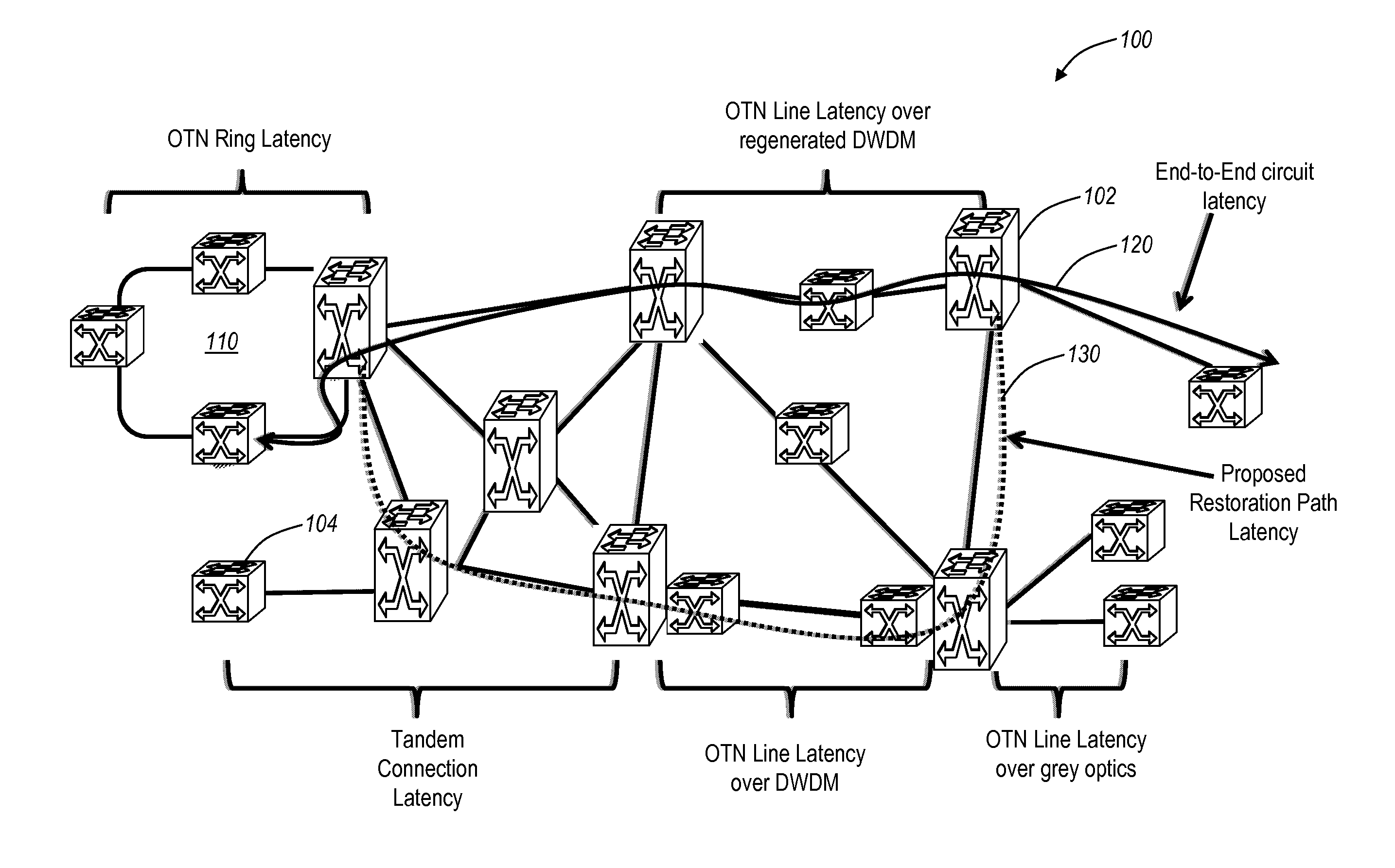
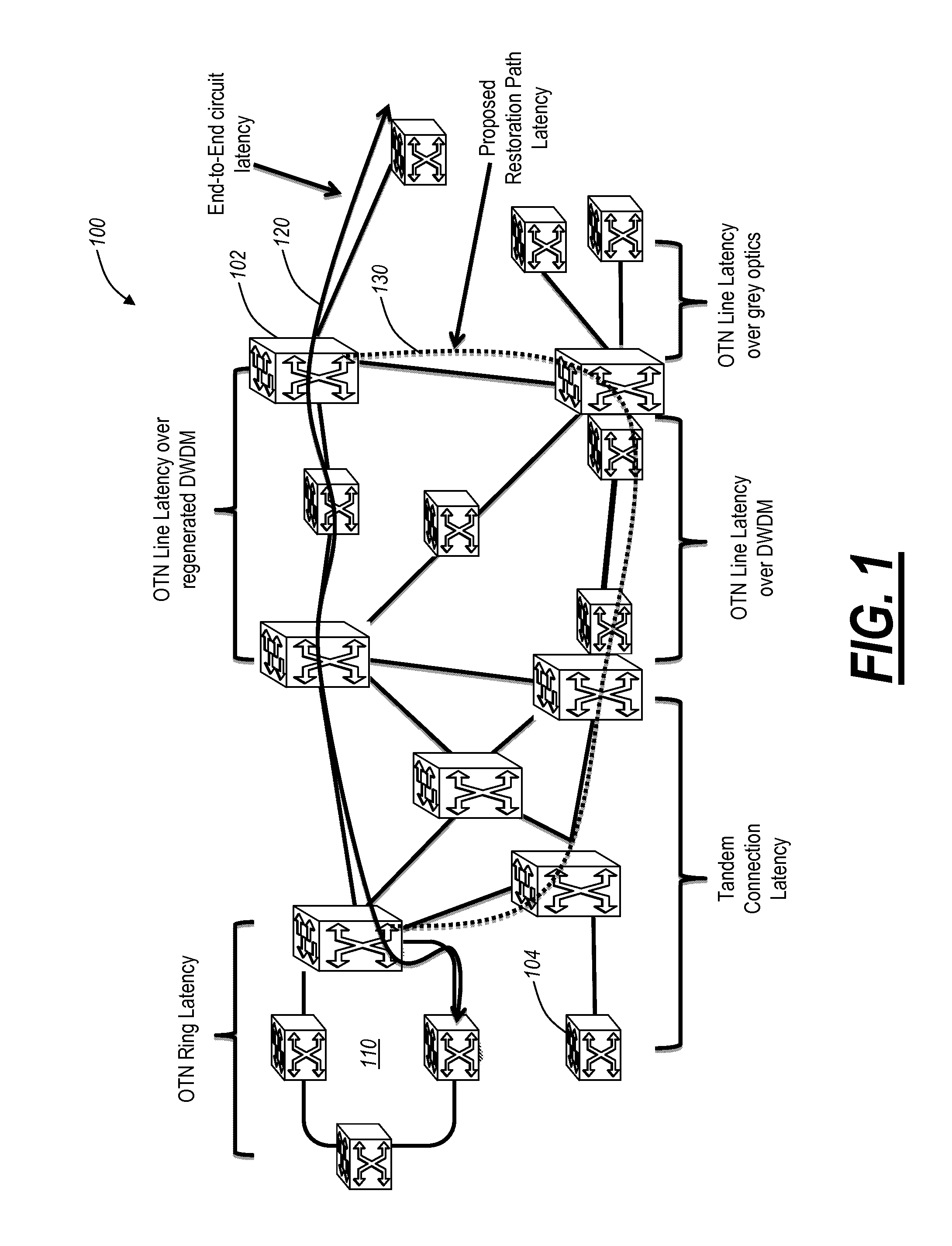
[0021]In various exemplary embodiments, the present invention provides systems and methods for making latency measurements and using these measurements in routing in optical networks. Latency is a measurement of time delay experienced in a system, such as an optical network including wavelength division multiplexers (WDM), optical switches, data routers and switches, and the like. In optically switched networks, latency may be critical to enterprise end-customers providing time critical applications, to storage providers with tight service level agreements, and the like. In an exemplary embodiment, a method is defined whereby two nodes sharing a line automatically determine whether both nodes are capable of making a latency measurement and then which node will initiate and which node participates in making the latency measurement. When measurements are possible between two nodes, an averaged value of multiple measurements may be made and used as a trusted value. When measurements ar...


PUM


Abstract

The present disclosure provides systems and methods for making latency measurements and using these measurements in routing in optical networks. In an exemplary embodiment, a method is defined whereby two nodes sharing a line automatically determine whether both nodes are capable of making a latency measurement and then which node will initiate and which node participates in making the latency measurement. In another exemplary embodiment, an on-demand latency measurement may be made between any two arbitrary nodes within a domain. Routing messages may be used to disseminate the latency of links via a signaling and routing protocol. Advantageously, the present invention provides measurement of latency and latency variation of customer circuits (i.e., SNCs) using an in-band, non-intrusive calculation with a high-degree of accuracy. Furthermore, the present invention may consider these calculations for circuit routing based on the latency and circuit acceptance based on maximum latency restrictions.

Description

CROSS-REFERENCE TO RELATED APPLICATION(S)[0001]This application is a continuation-in-part of commonly assigned and co-pending U.S. patent application Ser. No. 12 / 684,457 filed Jan. 8, 2010, and entitled “OPTICAL NETWORK REAL TIME LATENCY MEASUREMENT SYSTEMS AND METHODS,” the contents of which are incorporated in full by reference herein.FIELD OF THE INVENTION[0002]The present invention relates generally to optical networking. More particularly, the present invention relates to systems and methods for measuring latency and routing connections in an optical network based upon the measured latency among other criteria.BACKGROUND OF THE INVENTION[0003]Optical networks are being deployed in interconnected mesh configurations using signaling and routing between network elements for establishing and maintaining sub network connections (SNCs). Conventionally, in optical networks, delay (i.e., latency) is measured indirectly via, administrative weights (“admin weights”), manually determined ...

Claims


Application Information

Patent Timeline
Patent Type & Authority Applications(United States)
IPC IPC(8): H04B17/00
CPCH04J3/0682H04J2203/0058H04L45/121H04Q2011/0086H04L45/70H04Q11/0062H04L45/62
Inventor SMITH, ALEXANDER A.MADRAHALLI, VAGISHCONKLIN, RICHARD W.
Owner CIENA
Why Eureka
Try Eureka