
Steam turbine system and method for operating a steam turbine

a steam turbine and steam turbine technology, applied in steam engine plants, non-positive displacement engines, machines/engines, etc., can solve the problems that material of this kind has been largely considered unfeasible for manufacturing these turbine vanes

Active Publication Date: 2011-08-04
SIEMENS ENERGY GLOBAL GMBH & CO KG
View PDF5 Cites 9 Cited by
  • Summary
  • Abstract
  • Description
  • Claims
  • Application Information

AI Technical Summary

Benefits of technology

The present invention relates to a steam turbine system and an operating method that can improve its operation by controlling the supply of steam through an additional steam inlet device. This device can be controlled based on operating parameters detected at the steam turbine system, and it can be positioned at the entry to a low-pressure section of the turbine. By using this additional steam inlet device, excess ventilation can be avoided, reducing temperature stress on the turbine components and allowing for the use of lighter materials for the turbine vanes. The invention can be used in both industrial and large-scale steam turbine systems.

Problems solved by technology

Materials of this kind have previously largely been considered unfeasible for manufacturing these turbine vanes.

Method used


Image

  • Steam turbine system and method for operating a steam turbine
  • Steam turbine system and method for operating a steam turbine
  • Steam turbine system and method for operating a steam turbine

Examples


Embodiment Construction

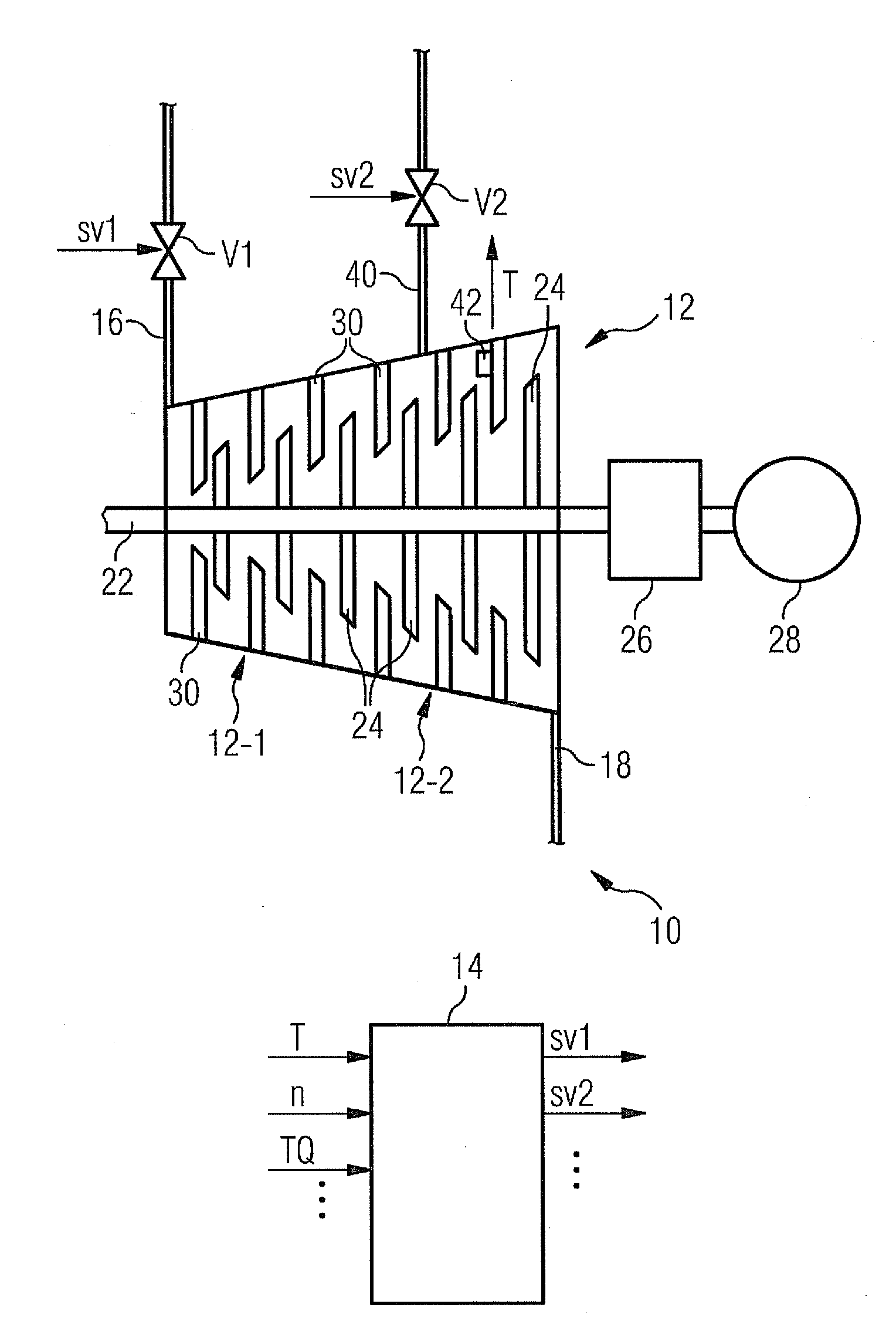
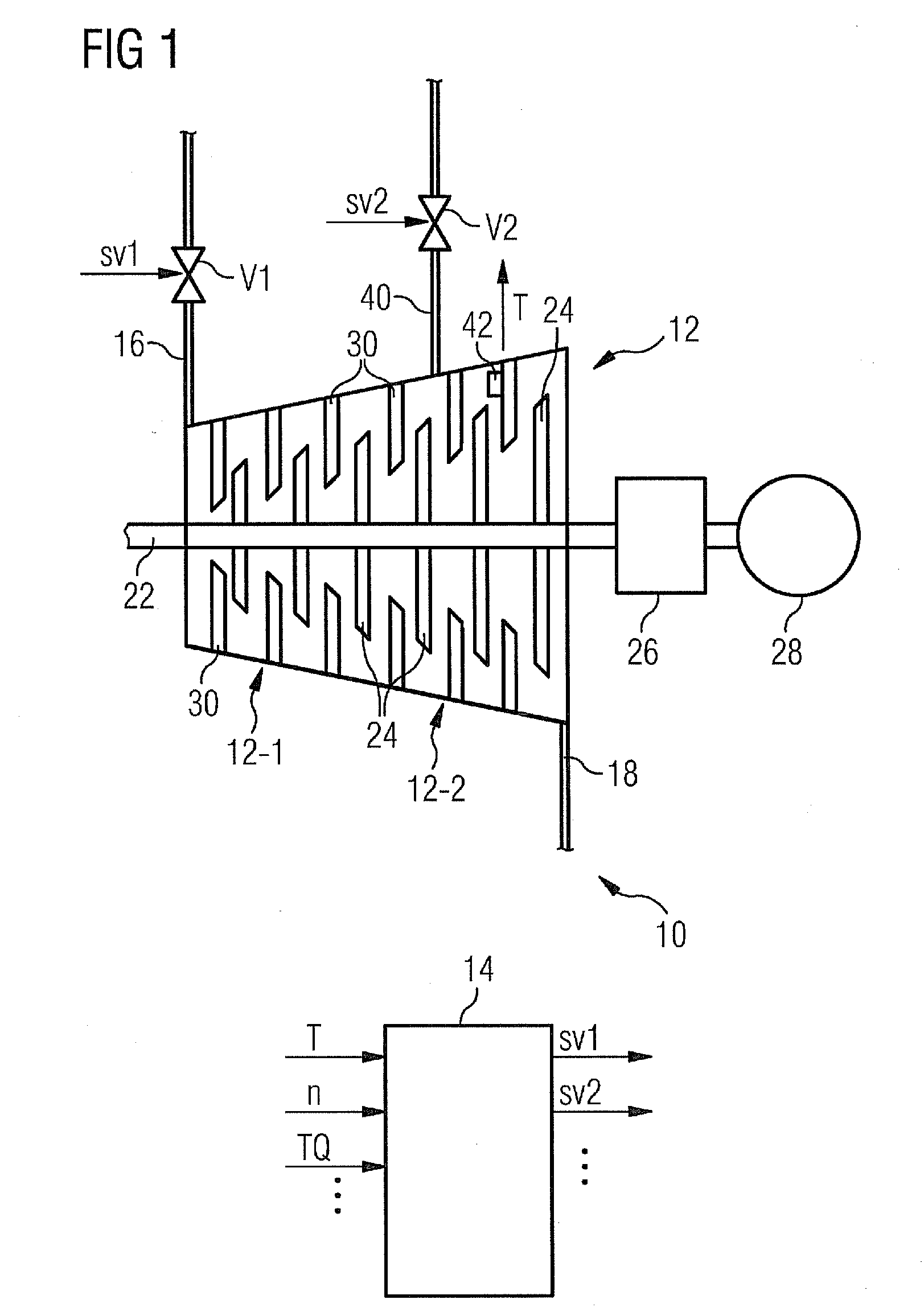
[0047]FIG. 1 shows a steam turbine system 10 having a steam turbine 10 and a control device 14 for controlling the steam turbine 12.

[0048]The turbine 12 comprises a high-pressure side steam feed pipe 16 for supplying fresh steam via a controllable valve V1 and a low-pressure side steam delivery pipe 18 which in the illustrated exemplary embodiment leads to a condenser (not shown) of a steam circuit from which fresh steam is produced again after the condensate has been heated.

[0049]During normal operation of the system 10 fresh steam, for example at a pressure of about 102 bar and a temperature of about 500° C., is supplied via the feed pipe 16 at the entry to the turbine 12. In a middle region of the turbine 12 the steam has a significantly reduced pressure and a significantly reduced temperature for example about 101 bar and about 200° C.) owing to preceding expansion. At a later stage the steam expands further and leaves at the exit of the turbine 12 again via the delivery pipe 18...


PUM


Abstract

A steam turbine system including a steam turbine is provided. The steam turbine system includes a high-pressure side steam inlet device, a low-pressure side steam device, and a control device for controlling the steam turbine. An additional steam inlet device is also included arranged between the high-pressure side steam inlet device and the low-pressure side steam device. The control device control a supply of steam via the additional steam inlet device as a function of operating parameters detected at the steam turbine system.

Description

CROSS REFERENCE TO RELATED APPLICATIONS[0001]This application is the US National Stage of International Application No. PCT / EP2009 / 059152, filed Jul. 16, 2009 and claims the benefit thereof. The International Application claims the benefits of European Patent Office application No. 10 2008 033 402.2 EP filed Jul. 16, 2008. All of the applications are incorporated by reference herein in their entirety.FIELD OF INVENTION[0002]The invention relates to a steam turbine system and to a method for operating a steam turbine.BACKGROUND OF INVENTION[0003]In a steam turbine the thermal energy from steam supplied to the turbine is converted into mechanical work. Known steam turbines of this kind comprise a high-pressure side steam inlet and a low-pressure side steam outlet. A control device for controlling at least the steam inlet, but usually for controlling additional system components as well, is also provided. A shaft extending through the turbine, what is referred to as the turbine rotor, ...

Claims


Application Information

Patent Timeline
Patent Type & Authority Applications(United States)
IPC IPC(8): F01K13/02
CPCF01D1/023F01D25/12F05D2260/2322F05D2270/3032F01K7/20
Inventor EPPENDORFER, JORGLEIDINGER, BERNDMANTEI, MARKUS
Owner SIEMENS ENERGY GLOBAL GMBH & CO KG
Learn More