Vision Guided Robotic Grommet Installation

a robotic grommet and installation technology, applied in the direction of metal-working machine components, metal working apparatus, manufacturing tools, etc., can solve the problems of repetitive stress injuries and fatigue of individuals, and achieve the effect of improving the safety and reliability of the installation process

Inactive Publication Date: 2011-09-01
ABB INC
View PDF52 Cites 42 Cited by
  • Summary
  • Abstract
  • Description
  • Claims
  • Application Information

AI Technical Summary

Problems solved by technology

Given the volume and force required, the fatigue and r...

Method used


Image

  • Vision Guided Robotic Grommet Installation
  • Vision Guided Robotic Grommet Installation
  • Vision Guided Robotic Grommet Installation

Examples


Embodiment Construction

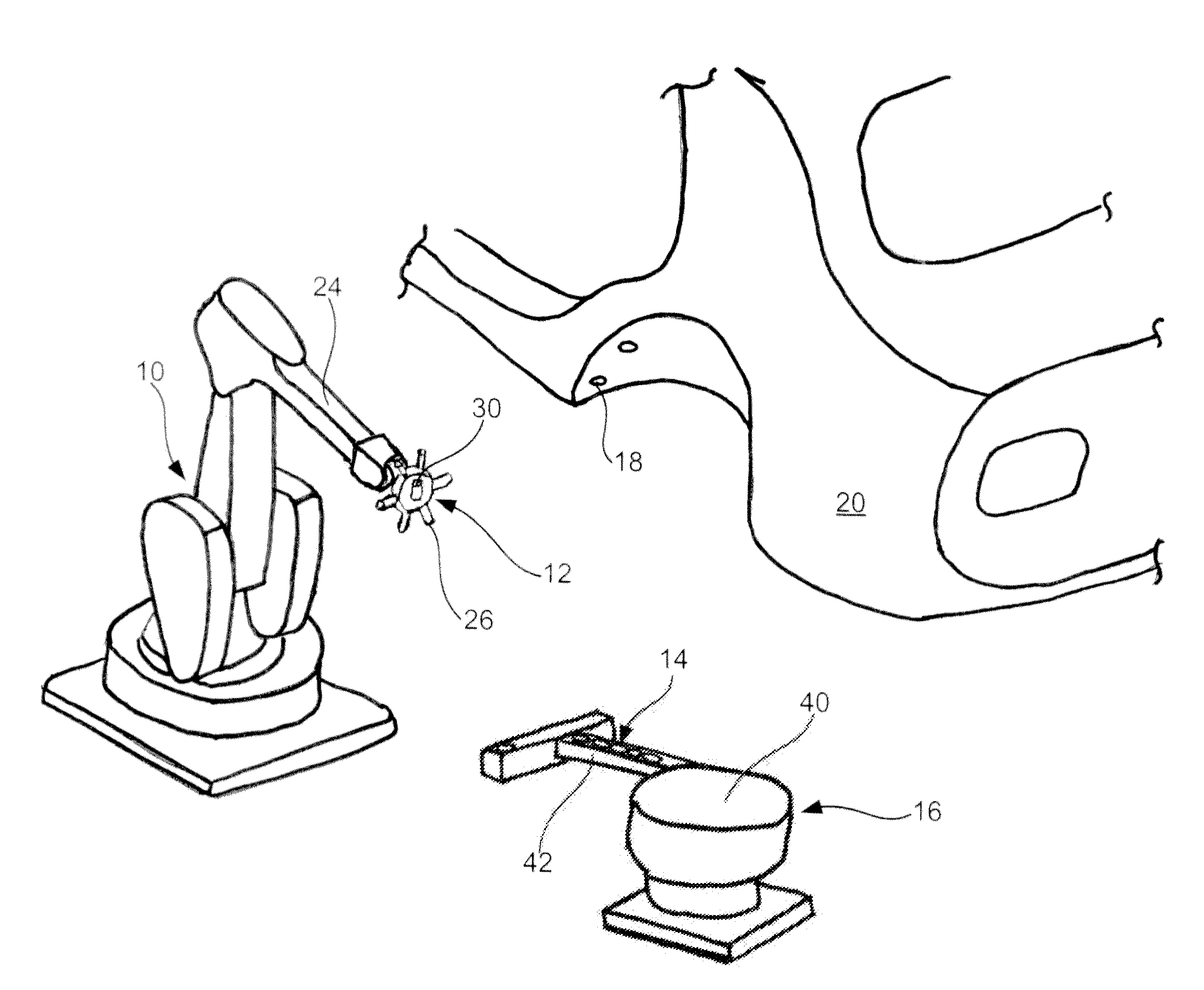
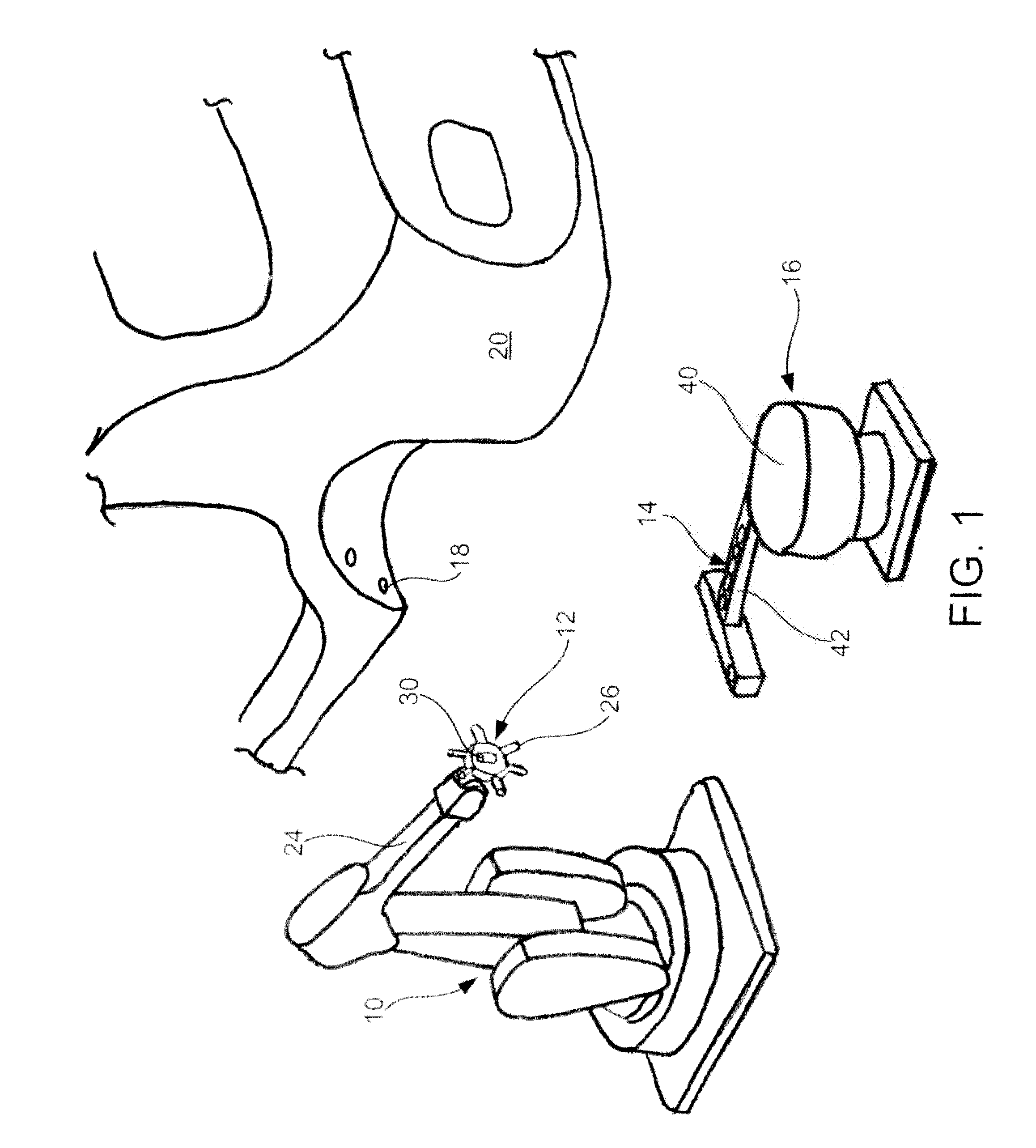
[0011]Generally, the present invention includes a process using a material handling robot(s) to install body sealing grommets or hole-plugs into holes in a vehicle. In operation, the robots are vision guided to find the location of the car body, install the grommets and then verify correct installation. Historically the issue with automating grommet installation has been hole location variation in a vehicle. In some instances, hole location can vary by approximately 5 to 25 mm in the x, y, and / or z planes. The present invention eliminates the hole location issue associated with the installation of grommets.

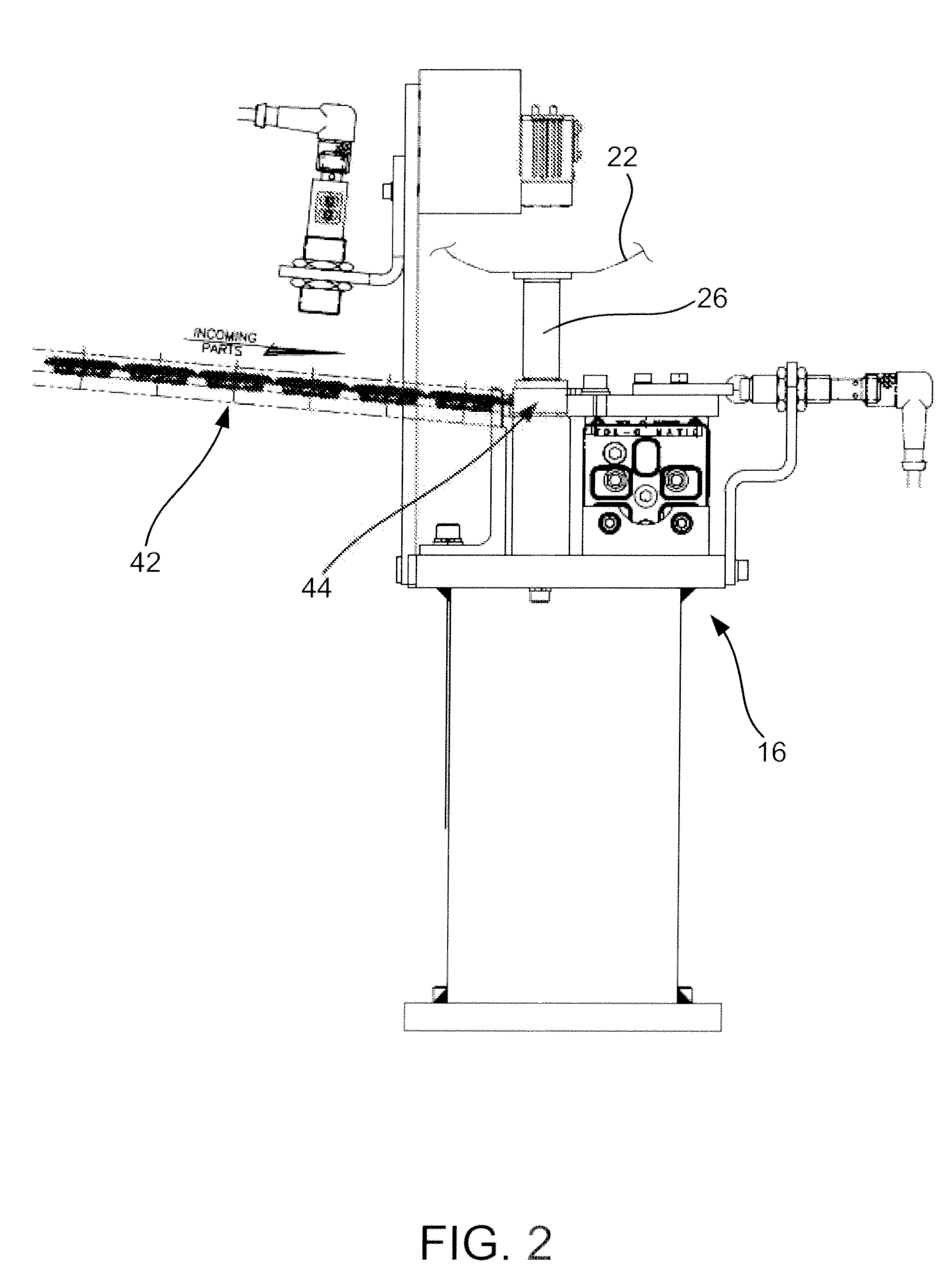
[0012]With reference now to FIG. 1, the system may include a robot 10. According to one embodiment, robot 10 is a six axis robot. Robot 10 includes a grommet tool 12 that selectively captures and installs grommets 14. The grommet tool 12 receives grommets from a grommet supplier 16 and installs the grommets 14 in holes 18 in a vehicle 20. It should be appreciated that, though FIG....


PUM

PropertyMeasurementUnit
Angleaaaaaaaaaa
Pressureaaaaaaaaaa
Areaaaaaaaaaaa

Abstract

A system and method installs grommets into vehicle grommet holes using vision a six axis robot with a grommet tool and a vision system. The robot arm moves to the general area of a grommet hole and then the vision system determines the exact hole location. Thereafter, the robot moves the grommet tool to the hole to install the grommet. Installation is then confirmed by the vision system.

Description

CROSS-REFERENCE TO RELATED APPLICATION[0001]This application claims the benefit of U.S. Provisional Patent Application No. 61 / 308,324, titled Vision Guided Robotic Grommet Installation and filed on Feb. 26, 2010, which is hereby incorporated by reference in its entirety.BACKGROUND[0002]Grommets are generally metal, plastic or rubber discs that may be inserted into a hole in an object. Grommets may be used to reinforce, seal or protect and cover the edges of the hole. Automobiles commonly include 50 or more holes that require an installed grommet. If 60 cars are assembled per hour, for 8 hrs in a day, a person could install 24,000 grommets per day. This number is compound by the amount of force that is required for grommet installation, which is approximately 100 Newtons. Given the volume and force required, the fatigue and repetitive stress injuries to individuals become problematic.[0003]Accordingly, there is a need in the art for an automated grommet installation system that elimi...

Claims


Application Information

Patent Timeline
IPC IPC(8): B23Q17/00B23P21/00
CPCB23P19/084B23Q17/2409B23Q17/2414Y10T29/53022B25J11/00Y10T29/49769B23Q17/2428
Inventor CONNOLLY, BRIAN E.
Owner ABB INC
Why Eureka
Try Eureka