This helps you quickly interpret patents by identifying the three key elements:
Problems solved by technology
Method used
Benefits of technology
Benefits of technology
[0012]The present invention, in consideration of the above points, has as its object the decrease of the heat loss and the suppression of variation of the cool air temperature accompanying positional adjustment of a seat.
Problems solved by technology
For this reason, the air-conditioned air (cool air) which is sucked into the air collection port of the slide duct ends up rising in temperature and the heat loss becomes greater.
Further, if changing the slide position of the vehicular seat in the vehicle longitudinal direction, the distance from the vent of the floor duct to the air collection port of the slide duct ends up changing, so the temperature of the air-conditioned air (cool air) which is supplied to the vehicular seat air-conditioning system ends up varying and the air-conditioning ability of the vehicular seat air-conditioning system ends up fluctuating.
Method used
Image
Click on the blue label to locate the original text in one second.
Reading with bidirectional positioning of images and text.
Examples
first embodiment
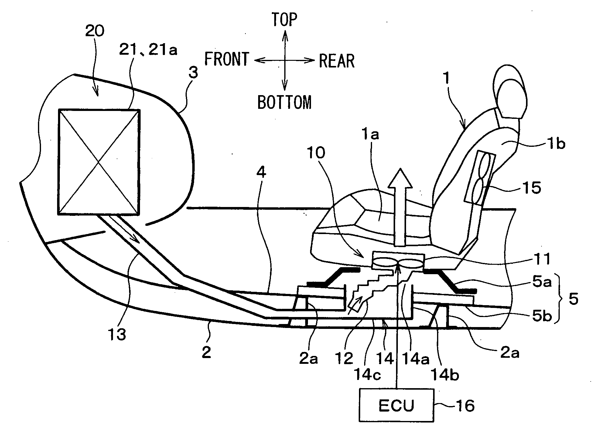
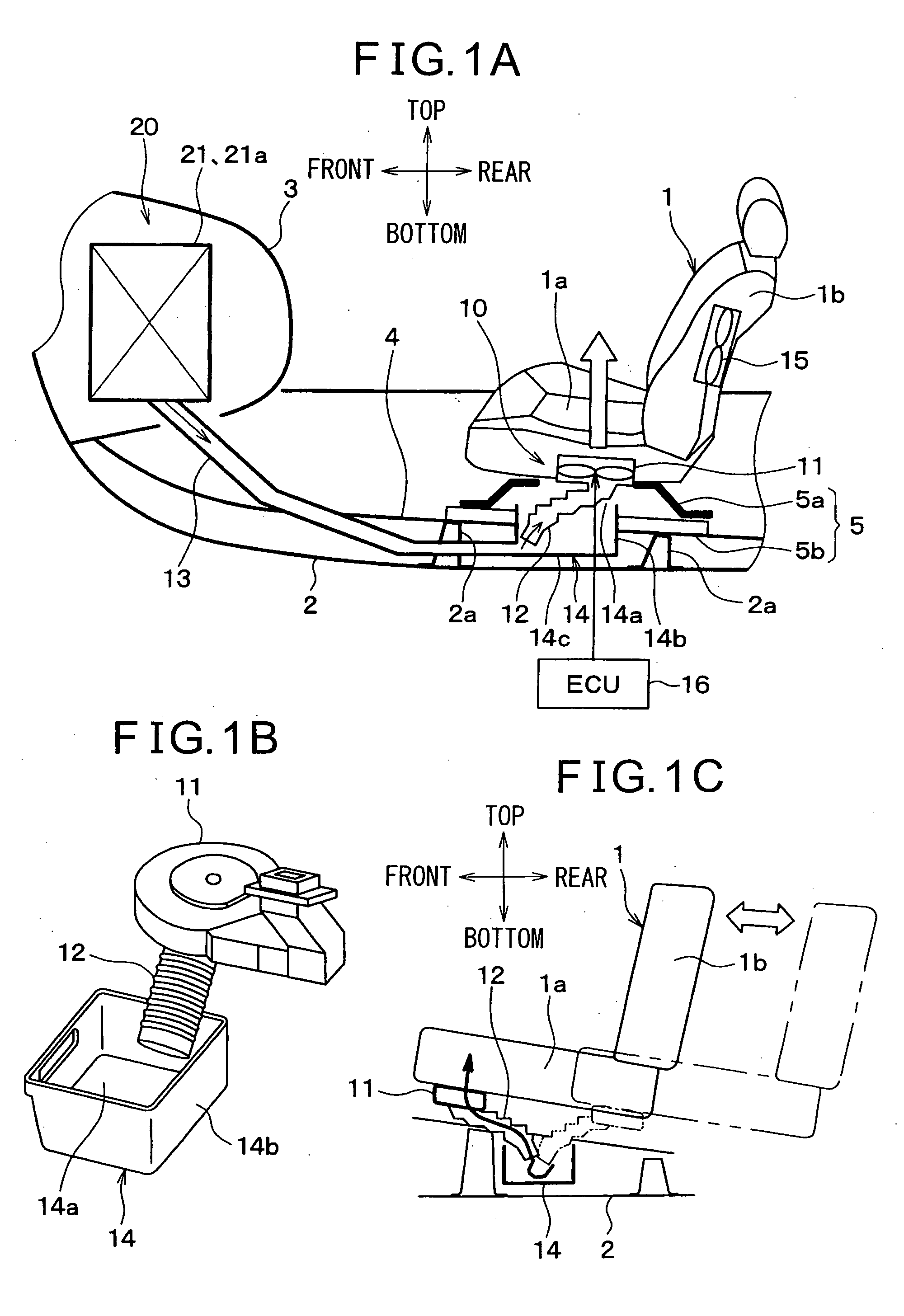
[0041]Below, a first embodiment of the present invention will be explained with reference to FIG. 1A, FIG. 1B, and FIG. 1C. The present embodiment applies vehicular seat air-conditioning systems of the present invention to the front seats (driver's seat and front passenger's seat).
[0042]FIG. 1A shows the general configuration of a vehicular seat air-conditioning system according to the present embodiment. The four arrows in FIG. 1A show vertical and horizontal directions of the vehicle.
[0043]Each vehicular seat air-conditioning system 10 is configured to blow cool air which is supplied from a vehicular air-conditioning unit 20 for air-conditioning a cabin space from the surface of a seat 1 for front seat use.
[0044]A blower 11 of each vehicular seat air-conditioning system 10 is built into a seat top 1a of the seat 1. The air blown from the blower 11 passes through an air passage (not shown) which is formed inside of the seat top 1a (cushion material) and an air vent opening (not sho...
second embodiment
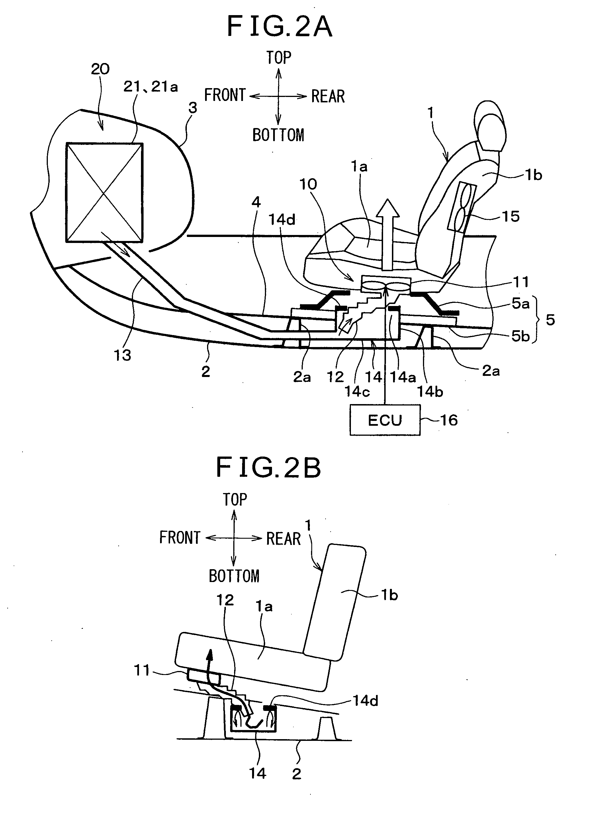
[0071]In the present second embodiment, as shown in FIG. 2A and FIG. 2B, the box-shaped part 14 in the first embodiment is formed with overhanging projections 14d which project out from the tops of the side walls 14b toward the inside of the opening part 14a. In the example of FIG. 2A and FIG. 2B, the projections 14d are formed at the top ends of the side walls 14b over the entire circumference of the opening part 14a.
[0072]Due to this, it is possible to facilitate the buildup of cool air at each box-shaped part 14 and keep cabin air from entering the box-shaped part 14 better and in turn is possible to further improve the air-conditioning ability of each vehicular seat air-conditioning system 10.
third embodiment
[0073]In the first embodiment, each seat air-conditioning duct 13 is directly connected to the air-conditioning case 21a, but in the present third embodiment, as shown in FIG. 3A, each seat air-conditioning duct 13 is connected to the air-conditioning case 21a through a rear face duct 22 forming the rear seat use blowing duct of the vehicular air-conditioning unit 20.
[0074]The rear face duct 22 extends from the air-conditioning case 21a toward the vehicle rear side. Specifically, the rear face duct 22 is arranged along a console 6 provided between the driver's seat and front passenger's seat between the driver's seat and front passenger's seat.
[0075]At the rear end of the rear face duct 22 (downstream side end), a rear face vent (not shown) is provided. The rear face vent mainly blows cool air toward the heads of the passengers at the rear seats. Note that, two sets of the rear face duct 22 and rear face vent are provided corresponding to the seat behind the driver's seat and the se...
PUM
Abstract
A vehicular seat air-conditioning system comprising a blower (11) which generates blown air, an intake duct (12) which is connected to an intake side of the blower (11), a seat air-conditioning duct (13) which is connected to the in-door air-conditioning unit (21) and in which cool air which was cooled by the in-door air-conditioning unit (21) flows, and a box-shaped part (14) which is formed by a separate member from chassis members forming the cabin space and which is connected to a downstream side end of the seat air-conditioning duct (13). The box-shaped part (14) have side walls (14b) which extend in a vertical direction and a bottom (14c) which closes a space surrounded by the side walls (14b) from the lower side, the top ends of the side walls (14b) form an opening part (14a) which opens facing the upper side in the vertical direction, and an upstream side end of the intake duct (12) is inserted into the inside of the box-shaped part (14) through the opening part (14a).
Description
BACKGROUND OF THE INVENTION[0001]1. Field of the Invention[0002]The present invention relates to a vehicular seat air-conditioning system which blows air from seats.[0003]2. Description of the Related Art[0004]In the past, this type of vehicular seat air-conditioning system was described in Japanese Patent Publication (A) No. 2008-168776. In this prior art, a blower is attached to a bottom surface of a seat, air blown from the blower flows through an air passage provided inside the seat, and the air is blown from a vent provided at the seat top to the passenger.[0005]In the blower, air-conditioned air (cool air) which is supplied from an in-door air-conditioning unit of a vehicular air-conditioning unit (main air-conditioning system for air-conditioning of the cabin space) is introduced. Due to this, the air-conditioned air (cool air) which is supplied from the in-door air-conditioning unit of the vehicular air-conditioning unit can be sent to the vehicular seat air-conditioning sys...
Claims
Application Information
Patent Timeline
Application Date:The date an application was filed.
Publication Date:The date a patent or application was officially published.
First Publication Date:The earliest publication date of a patent with the same application number.
Issue Date:Publication date of the patent grant document.
PCT Entry Date:The Entry date of PCT National Phase.
Estimated Expiry Date:The statutory expiry date of a patent right according to the Patent Law, and it is the longest term of protection that the patent right can achieve without the termination of the patent right due to other reasons(Term extension factor has been taken into account ).
Invalid Date:Actual expiry date is based on effective date or publication date of legal transaction data of invalid patent.

