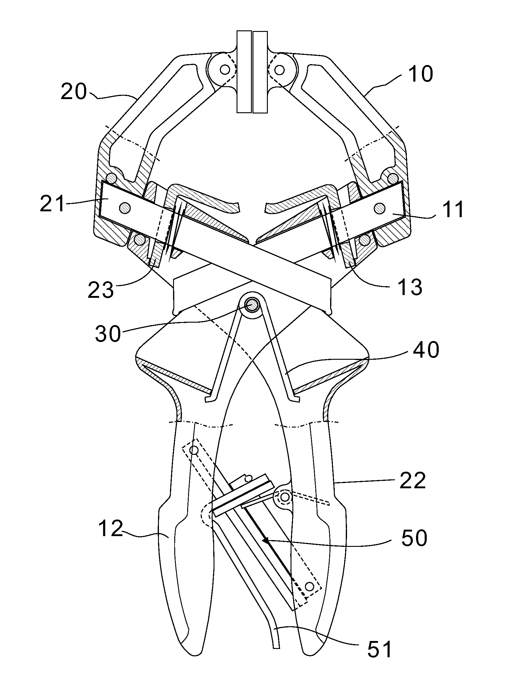
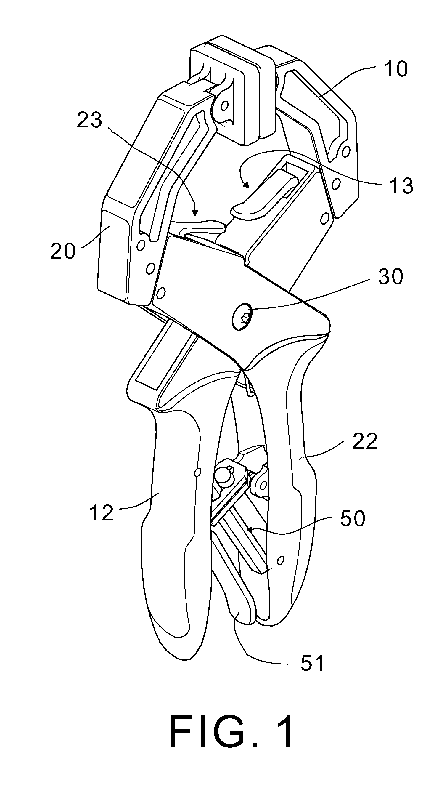
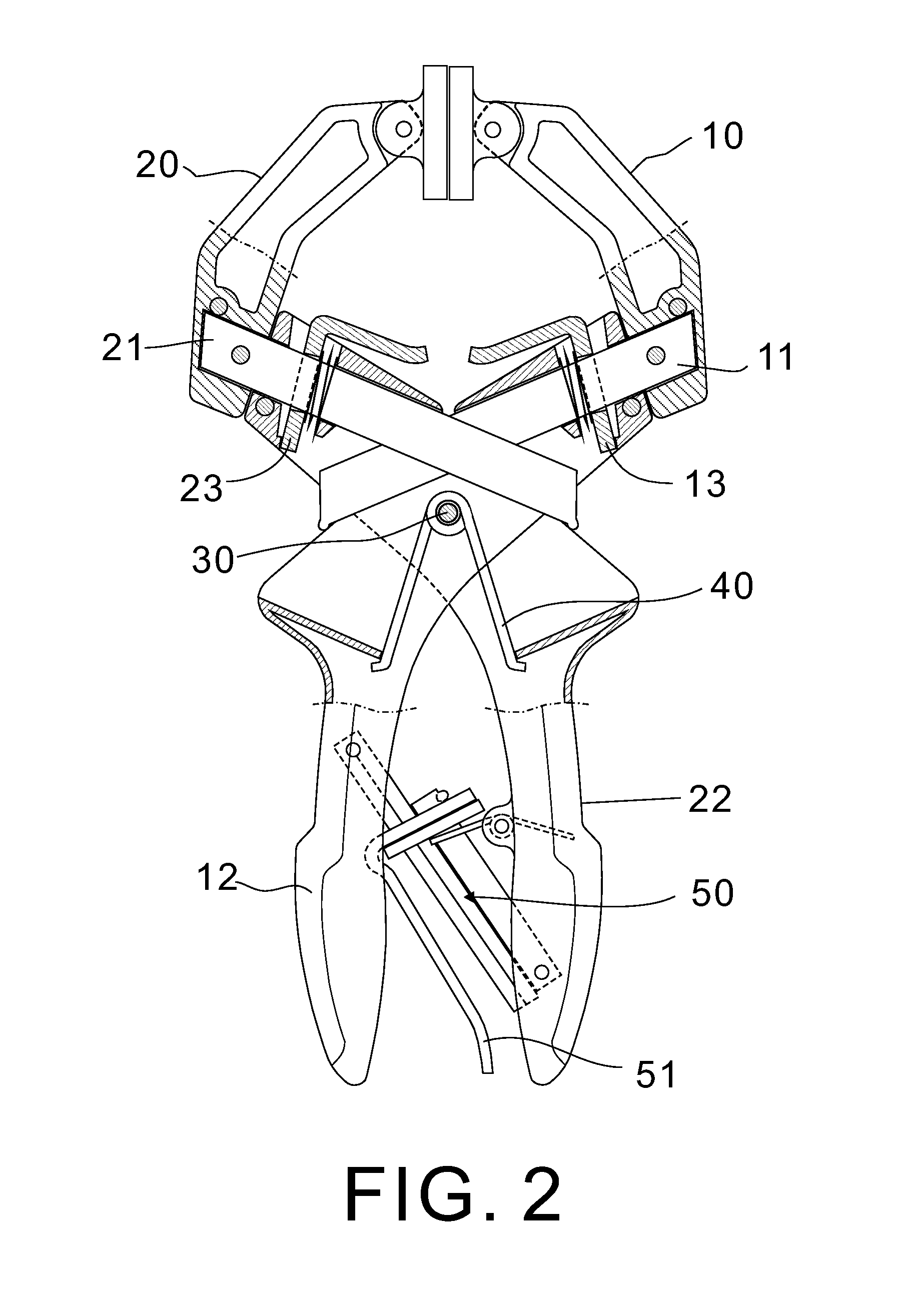
[0017]Referring to FIGS. 1 to 7, a locking pliers in accordance with the invention comprises the following components as discussed in detail below.
[0018]A first stationary jaw carrier 10 has a pivotal jaw 14 at one end. A second stationary jaw carrier 20 has a pivotal jaw 24 at one end. A bent first handle 12 and a bent second handle 22 are joined at a pivot joint 30 which is mounted with a torsion spring 40. The spring 40 has both ends anchored in two inner members of the first and second handles 12, 22 respectively so that the first and second handle 12, 22 can be resiliently pressed together.
[0019]A self-adjusting locking unit 50 is provided between the first and second handles 12, 22 and comprises a torsion spring 52 mounted on an inner surface of the second handle 22, a first bar 54 having one end pivotably secured to the inner surface of the second handle 22, a release lever 51 mounted on the other end of the first bar 54, a plate 53 urged between the other end of the spring 52 and a section of the release lever 51, and a second bar 55 having one pivotably secured to the inner surface of the first handle 11 and the other end slidably inserting through the section of the release lever 51 and the plate 53 to dispose engage with the first bar 54 thereabove. The self-adjusting locking unit 50 is locked with the jaws 14, 24 being engaged.
[0020]A housing portion of the first handle 12 extending from the pivot joint 30 has its end engaged with the other end of the first stationary jaw carrier 10 and a housing portion of the second handle 22 extending from the pivot joint 30 has its end engaged with the other end of the second stationary jaw carrier 20. The housing portion of the first handle 12 is partially engaged with inner surfaces of a portion of the housing portion of the first handle 22.
[0021]A first locking assembly 13 comprises a first slide bar 11 having one end fixedly secured to the other end of the first stationary jaw carrier 10 and the other end inserting into the housing portion of the first handle 12, a bent release lever member 61 having a holed portion put on the first slide bar 11 and an exposed portion for manual manipulation, and a torsion spring 62 biased between an internal member of the housing portion of the first handle 12 and the holed portion of the release lever member 61 for retaining the holed portion of the release lever member 61 in the housing portion of the first handle 12.
[0022]A second locking assembly 23 comprises a second slide bar 21 having one end fixedly secured to the other end of the second stationary jaw carrier 20 and the other end inserting into the housing portion of the first handle 12, a bent release lever member 61 having a holed portion put on the second slide bar 21 and an exposed portion for manual manipulation, and a torsion spring 62 biased between an internal member of the housing portion of the second handle 22 and the holed portion of the release lever member 61 for retaining the holed portion of the release lever member 61 in the housing portion of the second handle 22.
[0023]In an inoperative position, both the first and second slide bars 11, 21 are locked by the release lever members 61 and the jaws 14, 24 are engaged. In use, a person may press the release lever 51 to unlock the self-adjusting locking unit 50. As a result, the first and second handles 12, 22 are pushed apart by the springs 52 and 40. Also, the jaws 14, 24 are open and separated by a distance W (see FIG. 5).
[0024]Moreover, the person may press the release lever member(s) 61 to unlock the first locking assembly 13 and/or the second locking assembly 23 to further increase the distance. For example, as shown in FIG. 7, the person may press the exposed portion of the release lever member 61 to unlock the second locking assembly 23. Then the person may freely pull the second stationary jaw carrier 20 away from the housing portion of the second handle 22 (as indicated by arrow) until a desired distance (e.g., 3W as shown) between the jaws 14 and 24 is reached. After releasing the exposed portion of the release lever member 61, the release lever member 61 is immediately locked by urging the release lever member 61 against the second slide bar 21 as the spring 62 expands. As a result, the second locking assembly 23 is locked again.
[0025]Referring to FIG. 8, a locking pliers according to a second preferred embodiment of the invention is shown. The locking pliers of the second preferred embodiment has the following characteristics.
[0026]A first stationary jaw carrier 10 has a pivotal jaw 14 at one end. A second stationary jaw carrier 20 has a pivotal jaw 24 at one end. A bent first handle 12 and a bent second handle 22 are joined at a pivot joint 30 which is mounted with a torsion spring 40. The spring 40 has both ends anchored in two inner members of the first and second handles 12, 22 respectively so that the first and second handle 12, 22 can be resiliently pressed together.
[0027]A self-adjusting locking unit 50 is provided between the first and second handles 12, 22 and comprises a spring-actuated release lever 51 for manual manipulation for unlocking. A housing portion of the first handle 12 extending from the pivot joint 30 is integrally formed with the first stationary jaw carrier 10 and a housing portion of the second handle 22 extending from the pivot joint 30 has its end fixedly secured to the other end of the second stationary jaw carrier 20.
[0028]A spring-actuated locking assembly 23 comprises a slide bar 21 having one end fixedly secured to the other end of the second stationary jaw carrier 20 and the other end inserting into the housing portion of the second handle 22.
[0029]In an inoperative position, the slide bars 21 is locked by the locking assembly 23 and the jaws 14, 24 are engaged. In use, a person may press the release lever 51 to unlock the self-adjusting locking unit 50. As a result, the first and second handles 12, 22 are pushed apart by at least the expanding spring 40. Also, the jaws 14, 24 are open.
[0030]Moreover, the person may manually unlock the locking assembly 23. Then the person may freely pull the second stationary jaw carrier 20 away from the housing portion of the second handle 22 until a desired distance between the jaws 14 and 24 is reached. After releasing the locking assembly 23, the slide bar 21 is locked again.
[0031]While the invention herein disclosed has been described by means of specific embodiments, numerous modifications and variations could be made thereto by those skilled in the art without departing from the scope and spirit of the invention set forth in the claims.