Carrying case

a case and carrying handle technology, applied in the field of carrying cases, can solve the problems of compromising the convenience of transportation and requiring additional support structures

Inactive Publication Date: 2011-09-22
HONG FU JIN PRECISION IND (SHENZHEN) CO LTD +1
View PDF8 Cites 105 Cited by
  • Summary
  • Abstract
  • Description
  • Claims
  • Application Information

AI Technical Summary

Problems solved by technology

However, an additional support structure is required; this structure is placed under th...

Method used


Image

  • Carrying case
  • Carrying case
  • Carrying case

Examples


Embodiment Construction

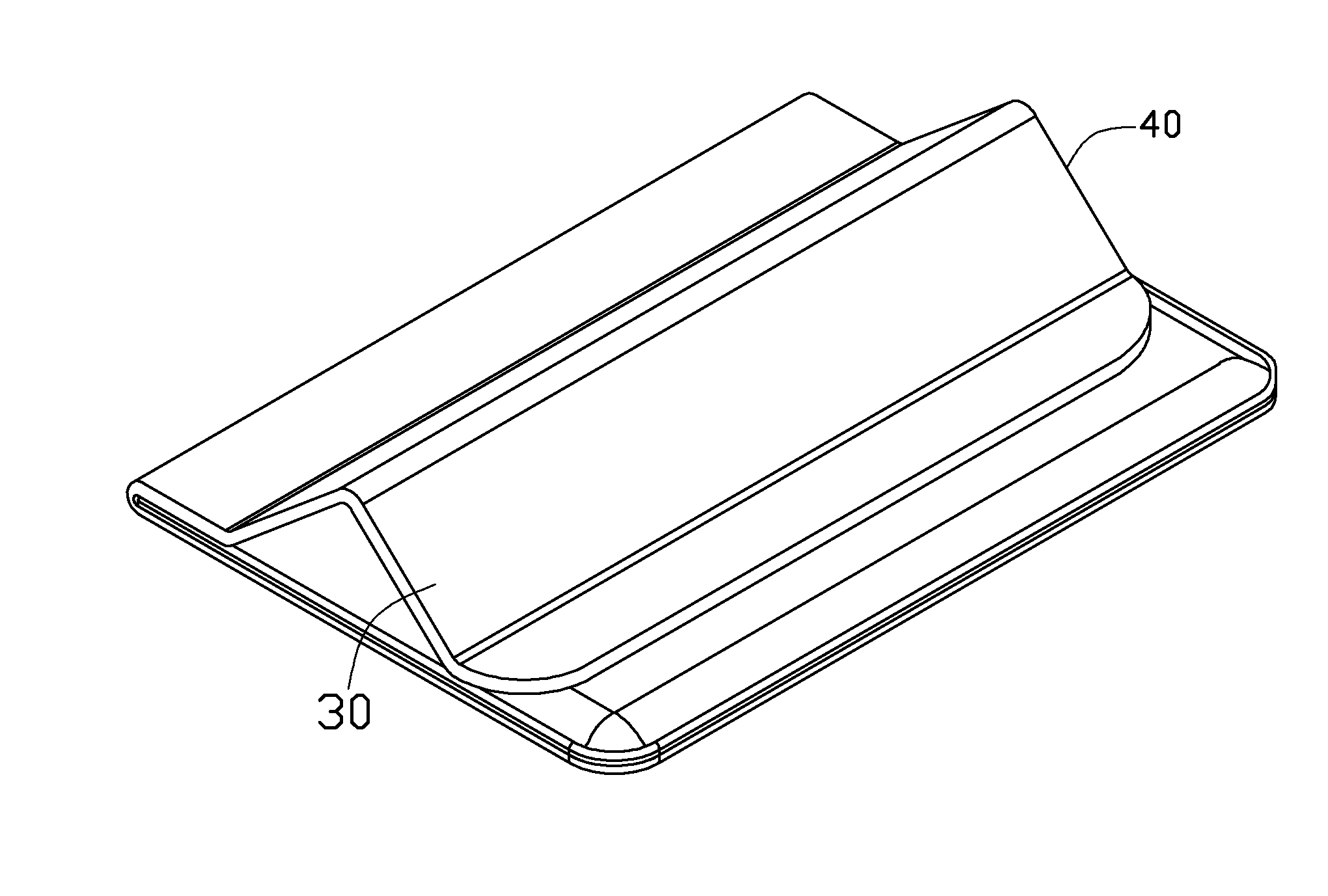
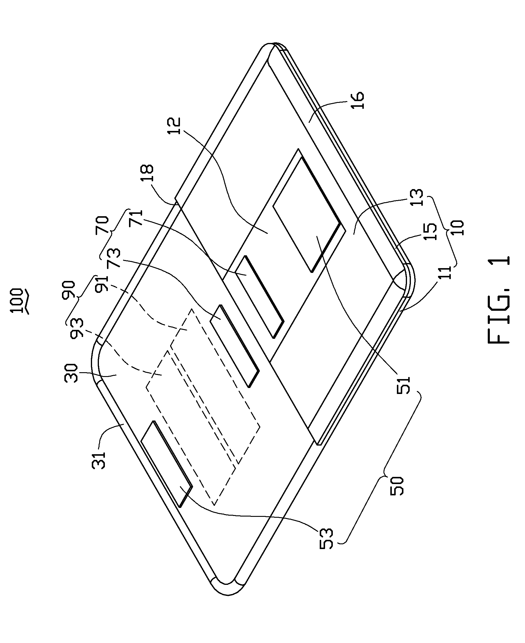
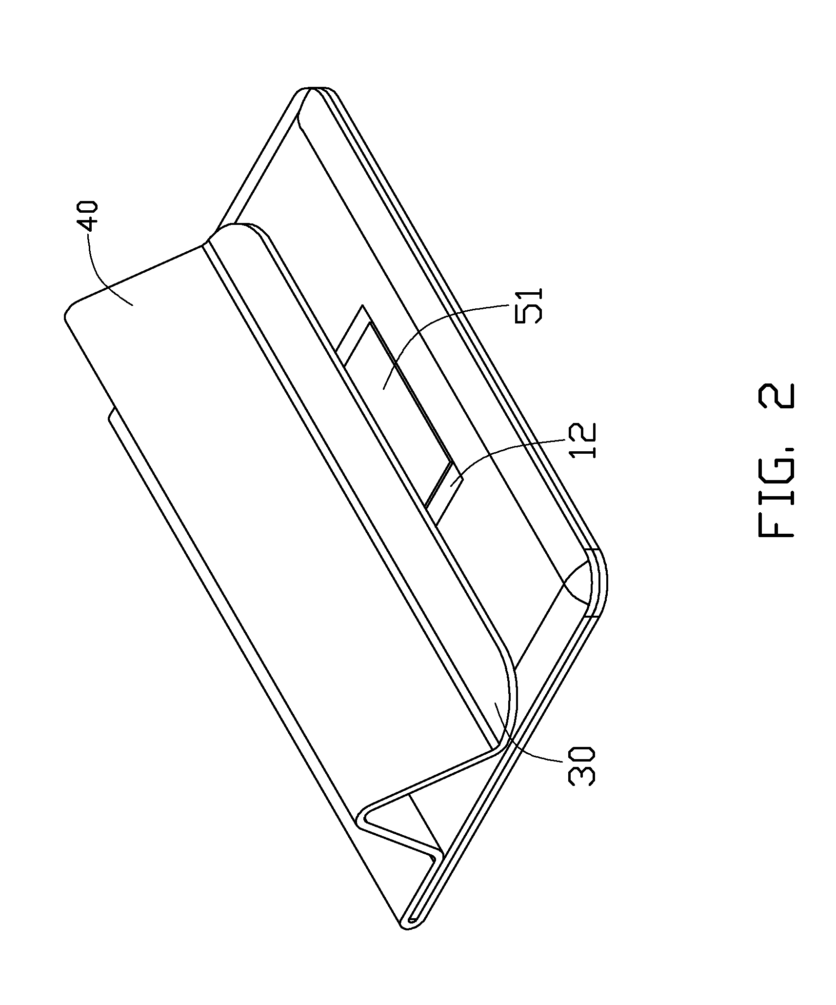
[0012]Referring to FIGS. 1 through 3, an embodiment of a carrying case 100 includes a main compartment 10, a cover 30 moveably positioned at a side of the main compartment 10, a first fastening assembly 50, a second fastening assembly 70 and supporting assembly 90. The carrying case 100 is used for carrying or supporting an electronic device 200 (FIG. 4), such as a notebook computer, projector or digital video disc player. In the illustrated embodiment, the electronic device 200 is a notebook computer.

[0013]The main compartment 10 is substantially rectangular. The main compartment 10 includes a bottom surface 11 and a top surface 13 opposite to the bottom surface 11 and interconnected thereto by three sidewalls 15. The bottom surface 11, the top surface 13 and two sidewalls 15 cooperatively define an entrance 18. The main compartment 10 forms a flexible frame 16 at edges on the top surface 13. The main compartment 10 further includes a reinforcement member 12 on an outer surface of ...


PUM


Abstract

A carrying case for an electronic device includes a main compartment receiving the electronic device and having an opening as an entrance, a cover foldably fixed on the main compartment for covering the opening, a first supporting member positioned on the cover and a second supporting member positioned on the cover and spaced from the first supporting member, a first engaging member and a first fixing member. The first supporting member and the second supporting member are capable of forming a V-shaped ridge structure when the cover is partially elevated above the main compartment and supporting the electronic device. The first engaging member is fixed on the first fixing member to maintain the V-shaped ridge structure.

Description

BACKGROUND[0001]1. Technical Field[0002]The present disclosure relates to device accessories and, particularly, to a carrying case for an electronic device.[0003]2. Description of the Related Art[0004]A frequently used carrying case for an electronic device includes a main compartment receiving the electronic device and a cover moveably positioned on the main compartment. When the electronic device is received in the main compartment, the cover can be fastened to the main compartment to prevent the electronic device from dropping out. The cover also can be released from the main compartment to take the electronic device out of the main compartment for using the electronic device.[0005]However, an additional support structure is required; this structure is placed under the electronic device, to adjust a viewing angle thereof, compromising convenience of transport.[0006]Therefore, there is room for improvement within the art.BRIEF DESCRIPTION OF THE DRAWINGS[0007]The components in the...

Claims


Application Information

Patent Timeline
IPC IPC(8): A47B81/00
CPCA45C3/02A45C9/00A47B23/043A45C2013/025A45C2200/15A45C13/02
Inventor HOU, HONG-QILEE, MING-CHANG
Owner HONG FU JIN PRECISION IND (SHENZHEN) CO LTD
Why Eureka
Try Eureka