Detecting device and detecting method for monitoring battery module

Active Publication Date: 2011-09-29
NAT CHUNG SHAN INST SCI & TECH
View PDF3 Cites 23 Cited by
  • Summary
  • Abstract
  • Description
  • Claims
  • Application Information

AI Technical Summary

Benefits of technology

[0016]Above all, in the battery module detecting device and the battery module detecting method of the invention, the voltage difference between two electrically connected electrodes on different battery units and the load current of the load can be measured when the battery module is powered. The equivalent resistance between these two electrodes can be instantly computed according to the voltage difference and the load current. This equivalent resistance can effectively show the conduction quality betwee

Problems solved by technology

If the electrodes are directly contacted, it will be inconvenient for disposing, using, or inspection and maintenance.
If the metal connecting rod is used to connect the electrodes, the problem that the conduction quality is hard to be controlled must be taken into consideration.
In this condition, if the battery module is continued to be used, the temperature of the loosed contacting points or surfaces will be high to cause the fire on the circuit or other electronic hazards.
Based on the above-mentioned limitations, it is hard to monitor the assembling quality of the battery module on time when the battery module is used.
On the other hand, during the assembling process, there will be some unclean substances (e.g., verdigris or electrolyte) on the surfaces of the metal connecting rod and electrodes to cause the increasing of the contact resistance between the metal connecting rod and

Method used


Image

  • Detecting device and detecting method for monitoring battery module
  • Detecting device and detecting method for monitoring battery module
  • Detecting device and detecting method for monitoring battery module

Examples


first embodiment

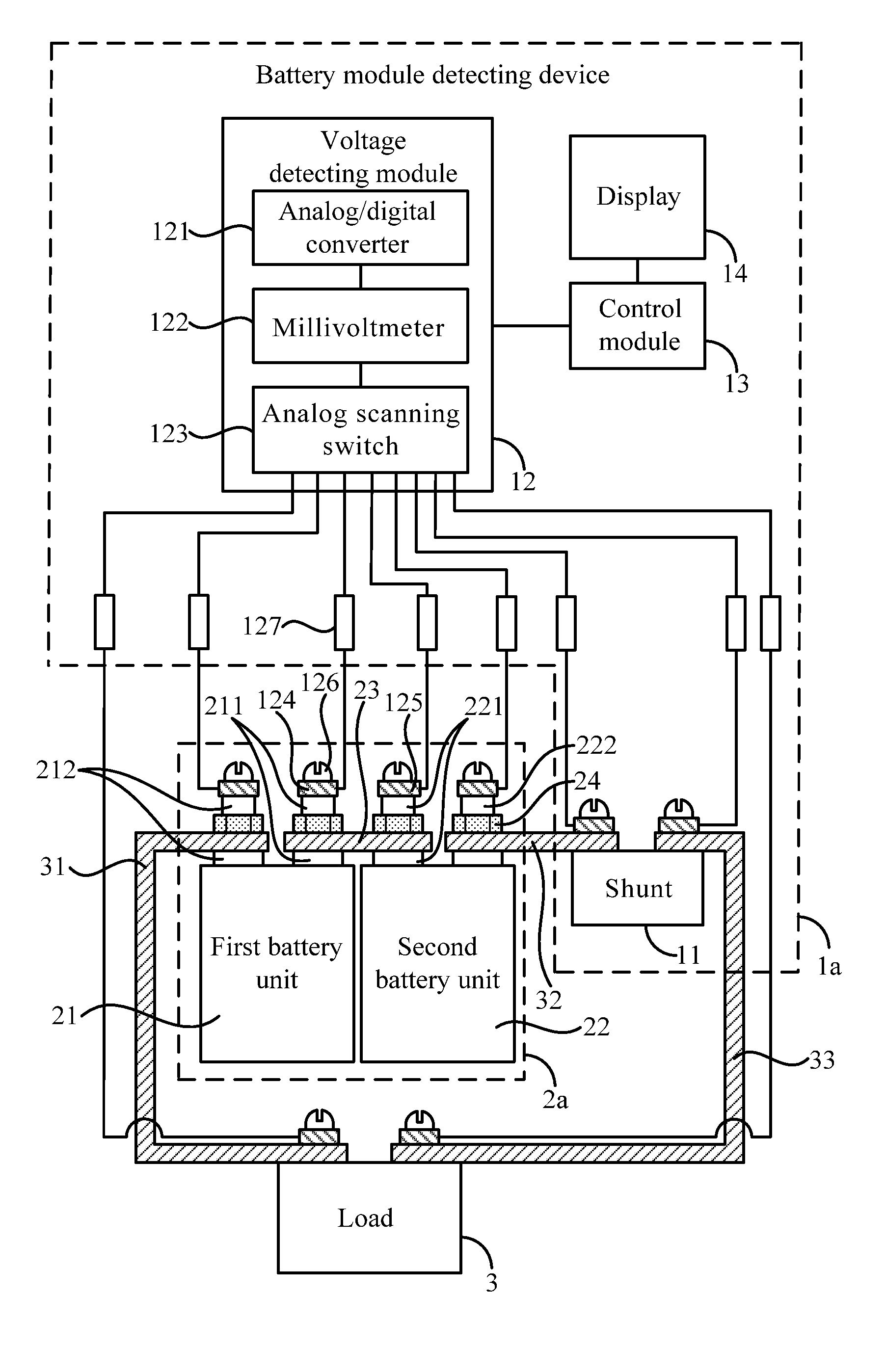
[0023]Please refer to FIG. 1. FIG. 1 shows the battery module detecting device 1a of the invention. The battery module detecting device 1a is used to test a battery module 2a, and the battery module 2a includes a first battery unit 21, a second battery unit 22, and a connecting device 23. The first battery unit 21 includes a positive electrode 211 and a first output electrode 212 of relative polarity. The second battery unit 22 includes a negative electrode 221 and a second output electrode 222 of relative polarity. The connecting device 23 electrically connects the positive electrode 211 of the first battery unit 21 and the negative electrode 221 of the second battery unit 22. The connecting device 23 is locked on the positive electrode 211 and the negative electrode 221 via two locking devices 24 respectively. In fact, the locking devices 24 can be a screw or other similar locking components. The battery module 2a is electrically connected to a load 3. More detail, one end of the ...

second embodiment

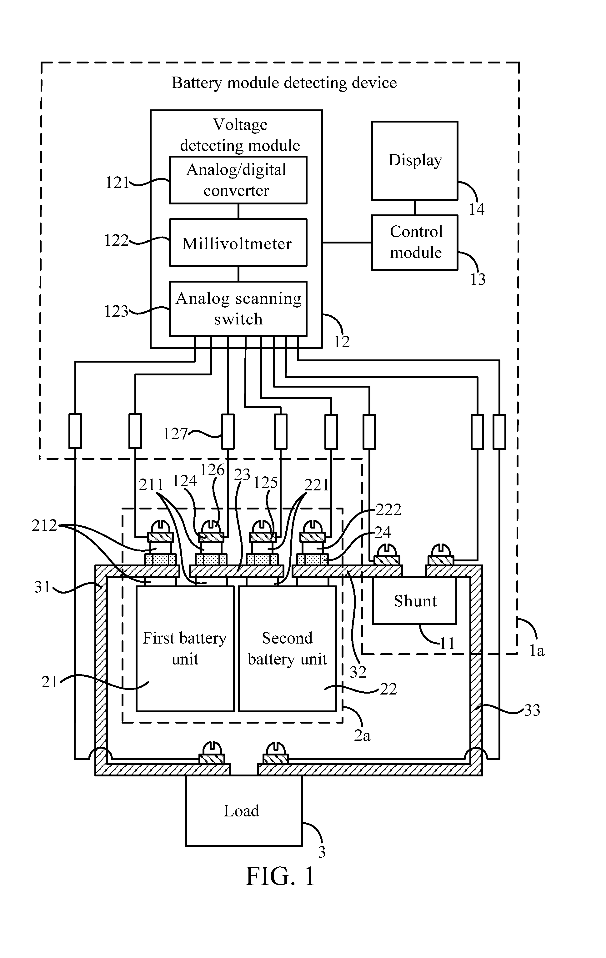
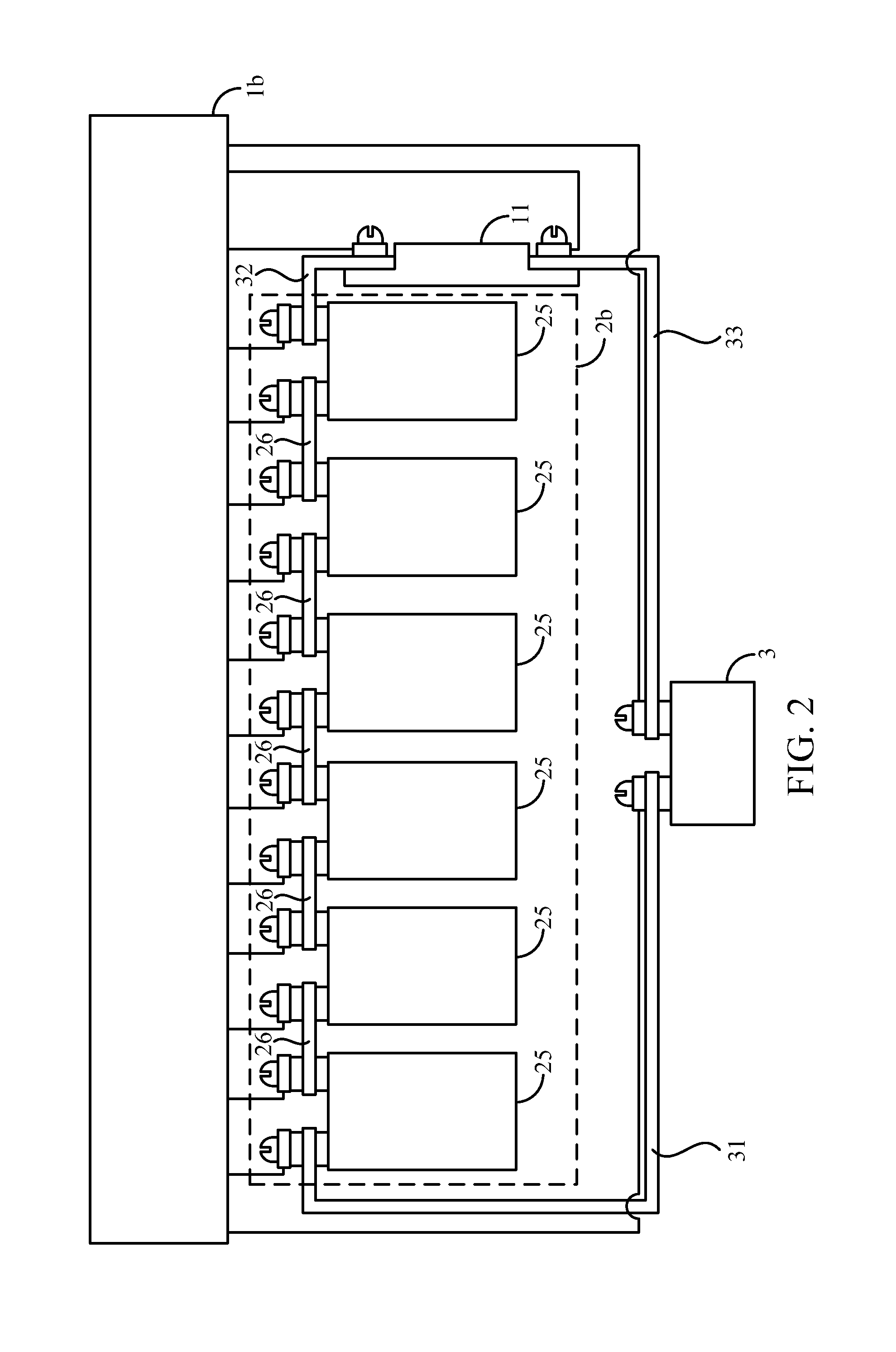
[0030]In order to explain the advantages of the battery module detecting device of the invention more clearly, the following will be explained cooperated with theorem and data. Please refer to FIG. 2, FIG. 2 shows the battery module detecting device 1b of the invention. In this embodiment, the battery module 2b is formed by six battery units 25 serially connected by the connecting device 26. The voltage provided by the battery units 25 is 3.33 volts. After the connecting devices 26 are properly disposed on the battery units 25, each connecting device 26 has the equivalent resistance of 0.2 mΩ.

[0031]If the current passing through the load 3 is 50 A, according to the power equation: (P=I×V), the total power provided by the battery module 2b under the load current 50 A is P2b=50 A×3.33V×6=999 W. According to the power equation: (P=I2×R), the connecting devices 26 has the initial power P26=50 A×50 A×0.2 mΩ=0.5 W. If one of the connecting device 26 is loosed or aged, the equivalent resis...


PUM


Abstract

A detecting device and a detecting method for monitoring a battery module are provided. The battery module is electrically connected to a load and includes a first battery unit, a second battery unit and a connecting device. The connecting device connects the positive electrode of the first battery unit to the negative electrode of the second battery unit. The detecting device includes a shunt, a voltage detecting module and a control module. The shunt is serial connected between the battery module and the load to measures the load current. The voltage detecting module measures the voltage difference across the connecting device between the positive electrode and the negative electrode. The control module computes the equivalent resistance across the connecting device between the positive electrode and the negative electrode according to the load current and the voltage difference. Therefore, the hazard caused by aging of the electric circuit can be prevented by monitoring the equivalent resistance, which infers the change of the assembly quality.

Description

BACKGROUND OF THE INVENTION[0001]1. Field of the Invention[0002]The invention relates to a battery module detecting device and a battery module detecting method, and more particularly, to a detecting device and a detecting method of measuring the resistance of the connecting device instantly when the battery module is used, so that the resistance can be an assembly quality indicator of the battery module.[0003]2. Description of the Prior Art[0004]A battery is a device of converting the energy generated by the chemical reaction into the electrical energy. A single battery unit can only provide a fixed range of voltage depending on the types of its chemical reactions. Therefore, in order to provide a power source of higher voltage or other specific voltage, in practical applications, several battery units are usually connected serially or in parallel to be a battery module, and then the power is outputted.[0005]A battery module formed by several battery units connected serially or in ...

Claims


Application Information

Patent Timeline
IPC IPC(8): G01N27/416
CPCG01R31/3624G01R31/3662G01R31/3658G01R31/3842G01R31/396G01R31/389
Inventor LIU, CHIN-CHUANMEI, LI-YANGYANG, FU-KWOWU, JONG-LIN
Owner NAT CHUNG SHAN INST SCI & TECH
Why Eureka
Try Eureka