Network Monitoring Server And Network Monitoring System

a network monitoring and server technology, applied in the field of network monitoring servers, can solve problems such as inability to determine whether or not to use, limited range of communication that can be confirmed, and inability to determine at all whether

Inactive Publication Date: 2011-09-29
HITACHI LTD
View PDF3 Cites 40 Cited by
  • Summary
  • Abstract
  • Description
  • Claims
  • Application Information

AI Technical Summary

Benefits of technology

[0011]The present invention has been made to solve the above problem, and aims at providing a network monitoring server and a network monitoring system, which can promptly carve up the failure factor by effectively prioritizing the ports to which the MEPs are assigned in a condition where the maximum number of MEPs is limited.
[0013]According to the network monitoring server and the network monitoring system of the present invention, the ports to which the MEPs are assigned are effectively prioritized in a condition where the maximum number of MEPs is limited, thereby enabling the failure factor to be promptly carved up.

Problems solved by technology

However, the above-mentioned method combining the ping and the Ethernet OAM together to carve up the failure factor has suffered from a problem on scalability.
However, in this method, a port of a core switch is selected preferentially, and a range where the communication can be confirmed is limited to the vicinity of the core switch.
This leads to such a problem that it cannot be determined at all whether the failure factor exists within the network, or not.

Method used


Image

  • Network Monitoring Server And Network Monitoring System
  • Network Monitoring Server And Network Monitoring System
  • Network Monitoring Server And Network Monitoring System

Examples


first embodiment

[0052]A network monitoring server according to a first embodiment of the present invention monitors a network in which all ports of all switches within the network belong to a single Ethernet network, and Ethernet frames can be transmitted and received between the servers connected to those ports. The network monitoring server according to the first embodiment of the present invention can be also applied to a network that belongs to a single VLAN in which all the ports of all the switches within the network a-re represented by the same virtual LAN (VLAN) identifier.

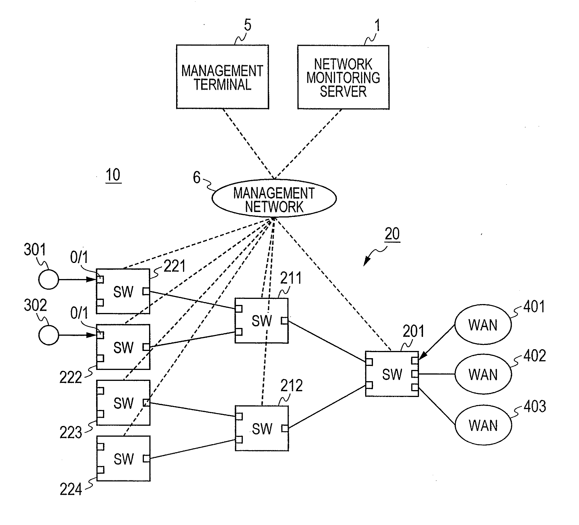
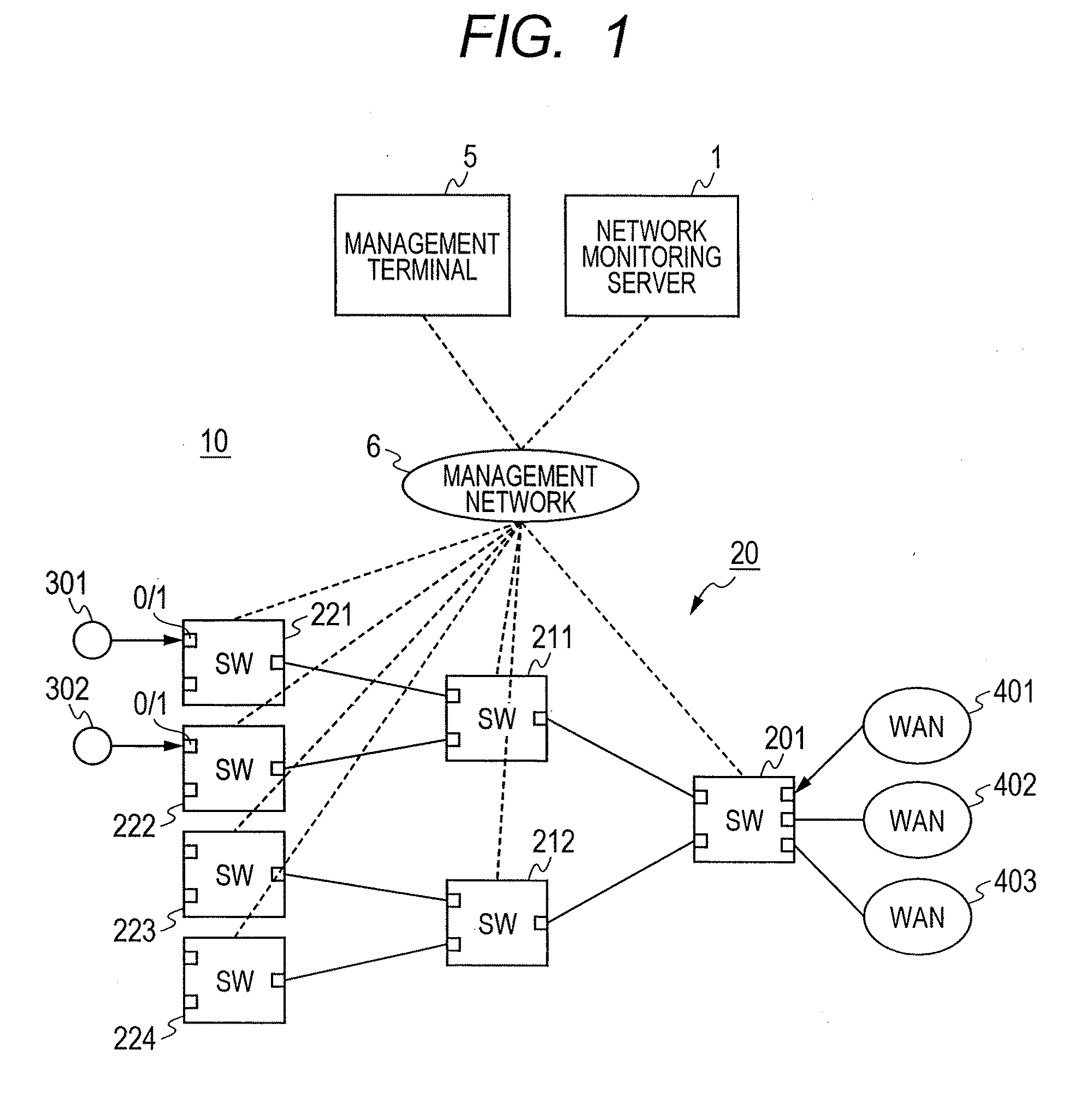
[0053]FIG. 1 illustrates a configuration example of a network monitoring system 10 according to the first embodiment of the present invention. The network monitoring system 10 includes a network monitoring server 1, switches to be monitored (hereinafter, referred to simply as “switches”) 201 to 224, servers 301 and 302, wide area networks (WANs) 401 to 403, a management terminal 5, and a management network 6.

[0054]The net...

second embodiment

[0180]A network monitoring server according to a second embodiment of the present invention outputs a procedure of changing the MEP configuration according to an instruction from the network manager. The network monitoring server instructs which port should be added to the list of the MEP-assigned ports at which time point, or which port should be deleted from the list of the MEP-assigned ports at which time point, on the basis of a change with time of the monitoring priority of each port.

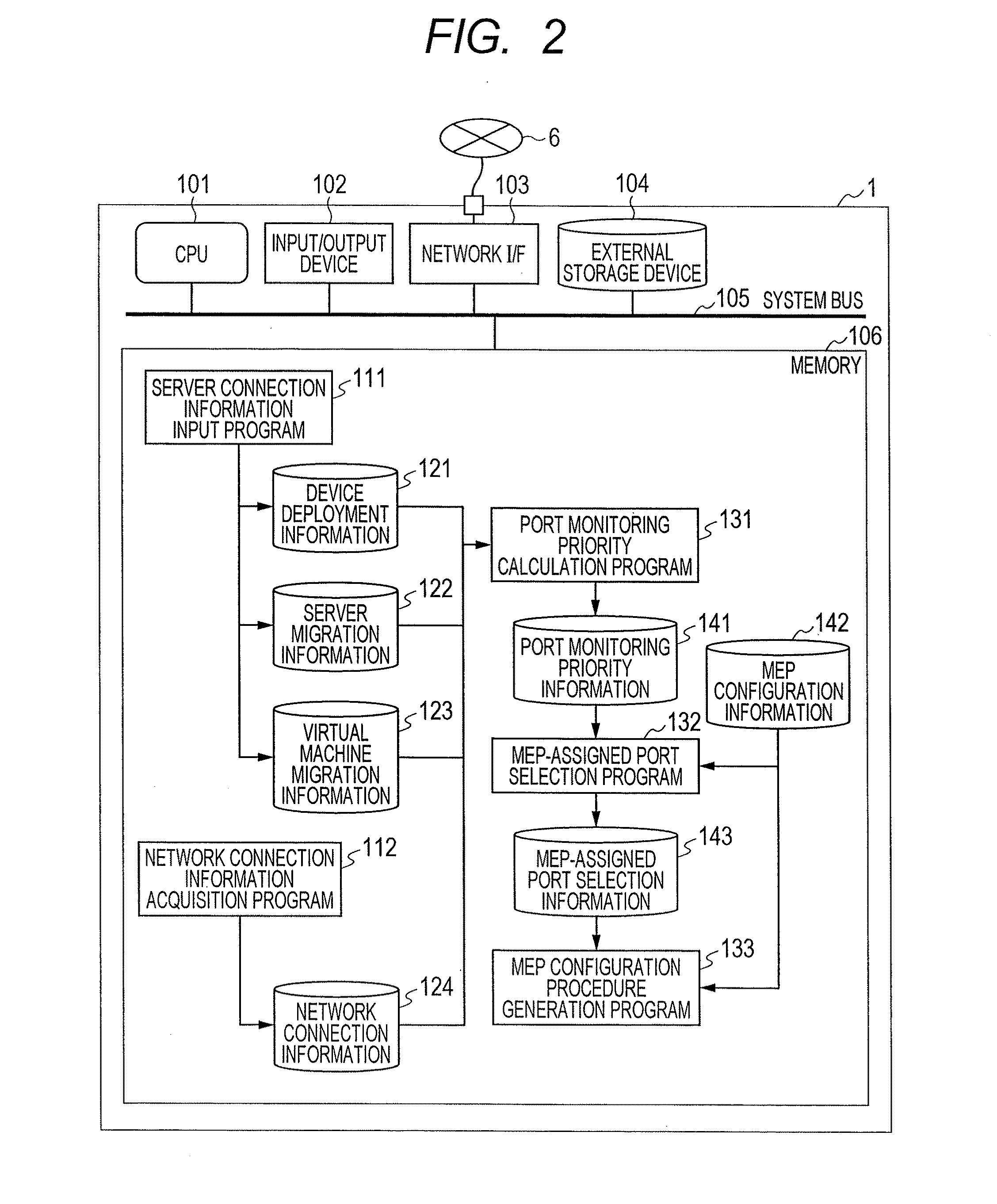
[0181]The second embodiment of the present invention is different from the above-mentioned first embodiment (refer to FIGS. 2 and 18) in the provision of MEP configuration schedule 144 and MEP configuration procedure 145 in the network monitoring server 1, and the operation of the MEP configuration procedure generation program 133. For that reason, the configuration of the network monitoring server 1 and the operation of the MEP configuration procedure generation program 133 will be mainly describe...

third embodiment

[0202]A network monitoring server according to a third embodiment of the present invention monitors a network that has been divided into plural logic networks by a VLAN. The network monitoring server selects the maximum number of assignable MEPs while suppressing the control load of the switch in the network using the VLAN.

[0203]According to the third embodiment of the present invention, the configuration of the network 20 to be monitored by the network monitoring server 1 and the operation of the MEP-assigned port selection program 132 are different from those in the above-mentioned first embodiment (refer to FIGS. 1 and 18). For that reason, the configuration of the network 20 and the operation of the MEP-assigned port selection program 132 will be mainly described, and the repetitive description of the common configurations and operation will be omitted.

[0204]FIG. 25 is a diagram illustrating a configuration example of the network 20 monitored by the network monitoring server 1 a...


PUM


Abstract

A failure factor can be promptly carved up by effectively prioritizing the ports to which MEPs are assigned in a condition where the maximum number of MEPs is limited. A network monitoring server monitors a network having plural switch devices. The plural switch devices each have a communication confirmation function using transmission and reception of a monitoring frame between ports. An upper limit is set to the number of ports to which maintenance end points (MEPs) are assignable among the respective ports of the plural switch devices. The network monitoring server calculates, for each of the plural switch devices, a monitoring priority corresponding to the probability of failures of a device connected to a network path including the port or the port, and generates data for displaying the calculated monitoring priority of each port in association with each port.

Description

CLAIM OF PRIORITY[0001]The present application claims priority from Japanese patent application JP 2010-069503 filed on Mar. 25, 2010, the content of which is hereby incorporated by reference into this application.FIELD OF THE INVENTION[0002]The present invention relates to a network monitoring server, and more particularly to a network monitoring server that manages a failure monitoring function provided in a network device in order to detect a failure in a communication network.BACKGROUND OF THE INVENTION[0003]Up to now, for the purpose of confirming a communication of a wide area network, a method in which monitoring frames are periodically transmitted from a port at an end point of a path, and the reception of the frames is confirmed at an opposed port has been widely used. In particular, in the Ethernet network, an Ethernet (registered trademark) OAM (operations administration maintenance, refer to IEEE 802.1ag Connectivity Fault Management (CFM)) is used.[0004]In addition, in ...

Claims


Application Information

Patent Timeline
Patent Type & Authority Applications(United States)
IPC IPC(8): G06F15/173H04L12/28H04L12/70H04M3/00H04M3/26
CPCH04L43/0817H04L41/142
Inventor OKITA, HIDEKIYOSHIZAWA, MASAHIROUEHARA, KEITARO
Owner HITACHI LTD
Why Eureka
Try Eureka