Suspension control apparatus and vehicle control apparatus

a technology of suspension control apparatus and control apparatus, which is applied in the direction of braking system, cycle equipment, instruments, etc., can solve the problems of inability to improve or reduce responsiveness and maximum amount at the same time, and the suspension control apparatus of the prior art, so as to reduce wheel load, safely control the operation of the vehicle, and reduce the effect of wheel load

Active Publication Date: 2011-10-06
HITACHI AUTOMOTIVE SYST LTD
View PDF4 Cites 12 Cited by
  • Summary
  • Abstract
  • Description
  • Claims
  • Application Information

AI Technical Summary

Benefits of technology

[0006]The present invention has been made to solve the above-mentioned problem in the prior art, which was found by inventors of the present invention, and has an object to provide a suspension control apparatus and a vehicle control apparatus, which are capable of controlling responsiveness to increase and reduce a wheel load and an absolute amount of an increase and a reduction in wheel load so as to more safely control an operation of a vehicle.

Problems solved by technology

Therefore, the responsiveness and the maximum amount cannot be both improved at the same time.
Thus, it is found that the suspension control apparatus of the prior art has a problem in that only any one of the responsiveness and the maximum amount can be improved or reduced during any of the compression stroke and the extension stroke of the shock absorber.

Method used


Image

  • Suspension control apparatus and vehicle control apparatus
  • Suspension control apparatus and vehicle control apparatus
  • Suspension control apparatus and vehicle control apparatus

Examples


first embodiment

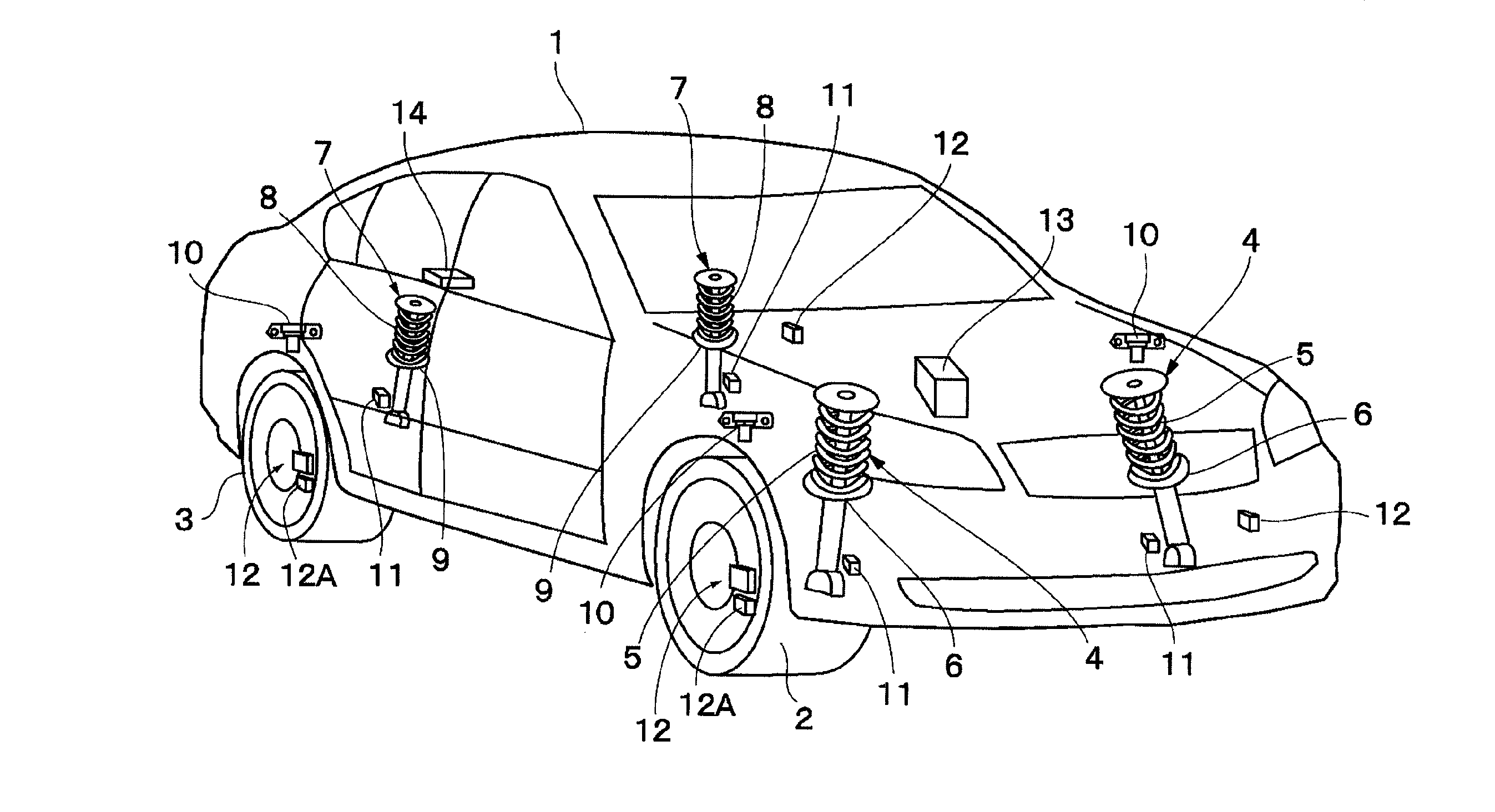
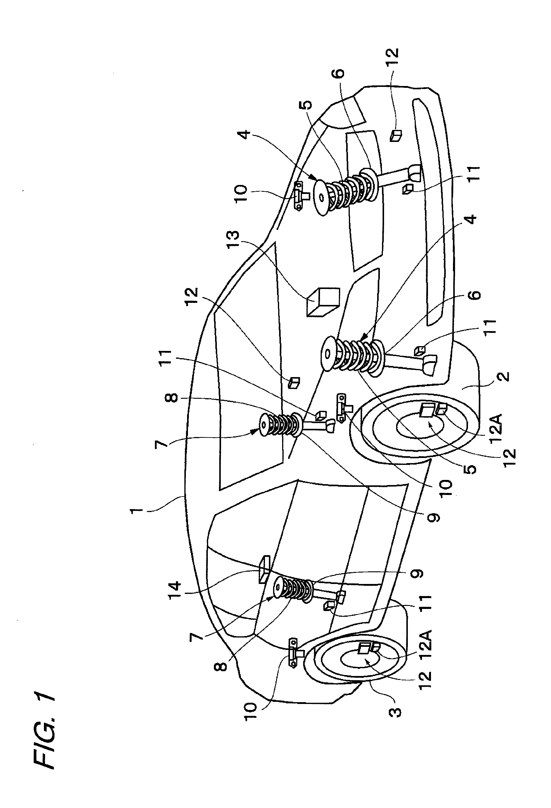
[0032]FIGS. 1 to 9 illustrate the present invention. In FIGS. 1 to 9, a vehicle body 1 constitutes a body of a vehicle. Below the vehicle body 1, for example, right and left front wheels 2 (only one thereof is illustrated) and right and left rear wheels 3 (only one thereof is illustrated) are provided.

[0033]A front-wheel side suspension apparatus 4 is provided between the left front wheel 2 and the vehicle body 1. Similarly, another front-wheel side suspension apparatus 4 is provided between the right front wheel 2 and the vehicle body 1. The left suspension apparatus 4 includes a left suspension spring 5 (hereinafter, referred to simply as “spring 5”), and a left damping-force adjustable shock absorber 6 (hereinafter, referred to as “damping-force variable damper 6”) provided in parallel to the spring 5 between the left front wheel 2 and the vehicle body 1. Similarly, the right suspension apparatus 4 includes a right spring 5, and a right damping-force variable damper 6 provided in...

second embodiment

[0103]Next, the damping-force computation processing for the wheel whose wheel load is desired to be reduced which is performed in S15 of FIG. 4, is described. The damping-force computation processing for the wheel whose wheel load is desired to be reduced is approximately the same as the damping-force computation processing for the wheel whose wheel load is desired to be increased. Therefore, only differences therebetween are described referring to FIG. 10.

[0104]In the computation of the damping force for the wheel whose wheel load is desired to be reduced, S47 of FIG. 10 is replaced by S47′, and a computation (computation performed in S57 of FIG. 10) for setting the damping-force command signal I to the hard command signal IH is performed in S47′. In S49′, S49 of FIG. 10 is replaced by S49′, and the damping-force command signal I is computed (computation in S56 of FIG. 10 is performed) so as to satisfy Formula 4. In S56′, S56 of FIG. 10 is replaced by S56′, and the damping-force ...

third embodiment

[0129]For example, during a period of time between 0 and Tc1 shown in FIG. 15, the relative acceleration “a” is negative as indicated by a characteristic line 118 shown in a solid line and the relative velocity “v” is also negative as indicated by a characteristic line 121 shown in a solid line. Therefore, during this period of time, the damping-force command signal I is set to the hard command signal IH by the processing performed in S126, S127, and S128 shown in FIG. 13 so as to increase the wheel load of the corresponding wheel during the compression stroke. Therefore, for example, during the period of time between 0 and Tc1, as indicated by a characteristic line 115 shown in a solid line, the characteristic of the wheel load is set to the wheel-load characteristic (characteristic in which the wheel load increases rapidly as compared with the wheel load indicated by the characteristic line 116 in the case where the damping force is fixed to the soft side) similar to the wheel-lo...


PUM


Abstract

A suspension control apparatus selectively performs at least one of: compression-stroke control performed when a wheel load is increased, for setting a damping-force characteristic of at least one of damping-force variable dampers, which is provided on a side of at least one wheel whose wheel load is to be increased among a plurality of wheels, to a hard side in an early stage of a compression stroke and switching the damping-force characteristic to a soft side in a latter stage of the compression stroke; extension-stroke control performed when the wheel load is increased, for setting the damping-force characteristic to the soft side in an early stage of an extension stroke and switching the damping-force characteristic to the hard side in a latter stage of the extension stroke; compression-stroke control performed when the wheel load is reduced, for setting the damping-force characteristic of at least one of the damping-force variable dampers, which is provided on a side of at least one wheel whose wheel load is to be reduced, to the soft side in the early stage of the compression stroke and switching the damping-force characteristic to the hard side in the latter stage of the compression stroke; and extension-stroke control performed when the wheel load is reduced, for setting the damping-force characteristic to the hard side in the early stage of the extension stroke and switching the damping-force characteristic to the soft side in the latter stage of the extension stroke.

Description

BACKGROUND OF THE INVENTION[0001]The present invention relates to a suspension control apparatus and a vehicle control apparatus, which are mounted to, for example, a vehicle such as a four-wheel automobile so as to be suitably used for damping the vibrations of the vehicle.[0002]In general, a suspension control apparatus is mounted to a vehicle such as an automobile as described in, for example, Japanese Patent Application Laid-open No. 2003-11635. The suspension control apparatus includes a damping-force adjustable shock absorber provided between a vehicle-body side and each axle side. A damping-force characteristic obtained by the shock absorber is variably controlled according to a vehicle attitude which is changed along with a braking operation of a brake or the like.[0003]The above-mentioned type of suspension control apparatus of the prior art is used in combination with a vehicle stability control apparatus to perform control for variably switching the damping-force characte...

Claims


Application Information

Patent Timeline
Patent Type & Authority Applications(United States)
IPC IPC(8): B60G17/06
CPCB60T8/1755B60T2260/06B60G17/08B60G2400/102B60G2400/202B60G2800/94B60G2400/39B60G2400/518B60G2400/5182B60G2500/10B60G2500/104B60G2400/252B60G17/015
Inventor HARADA, NAOFUMIKUMEMURA, YOICHIGANKAI, TATSUYA
Owner HITACHI AUTOMOTIVE SYST LTD
Why Eureka
Try Eureka