
Suture passer assembly

a technology of assembly and suture, applied in the field of suture passer assembly, can solve the problems of limiting the number of positions from which the surgical instrument may be operated, and limiting the surgeon's ability to perform surgery

Inactive Publication Date: 2011-10-13
HOWMEDICA OSTEONICS CORP
View PDF7 Cites 56 Cited by
  • Summary
  • Abstract
  • Description
  • Claims
  • Application Information

AI Technical Summary

Problems solved by technology

This requires that the surgical instrument be positioned according to the constraints of the surgical site, which limits the number of positions from which the surgical instrument may be operated.
As a result, there are often constraints on the surgeon that result from the particulars of the surgery and the surgical instrument itself.

Method used


Image

  • Suture passer assembly
  • Suture passer assembly
  • Suture passer assembly

Examples


Embodiment Construction

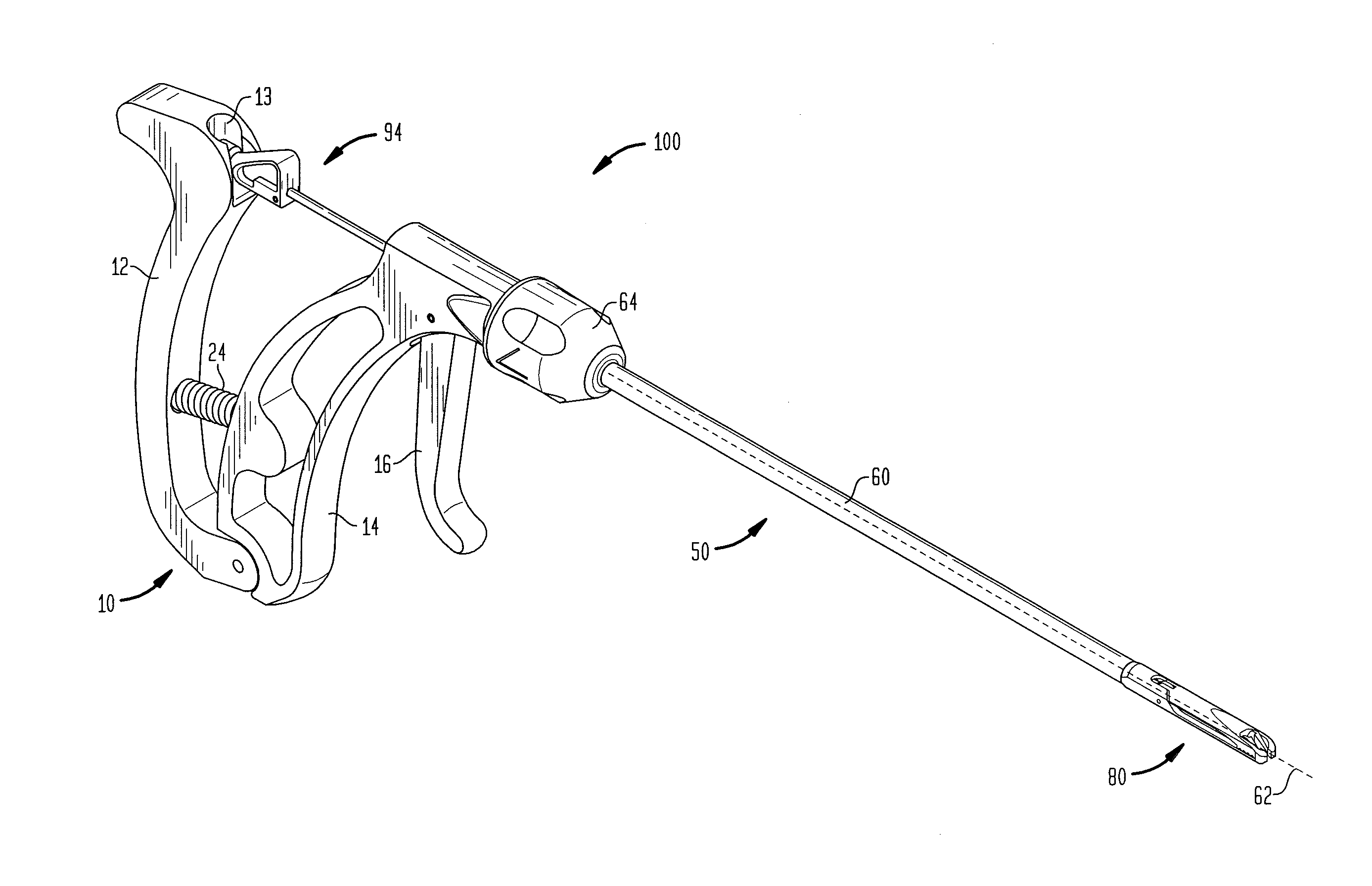
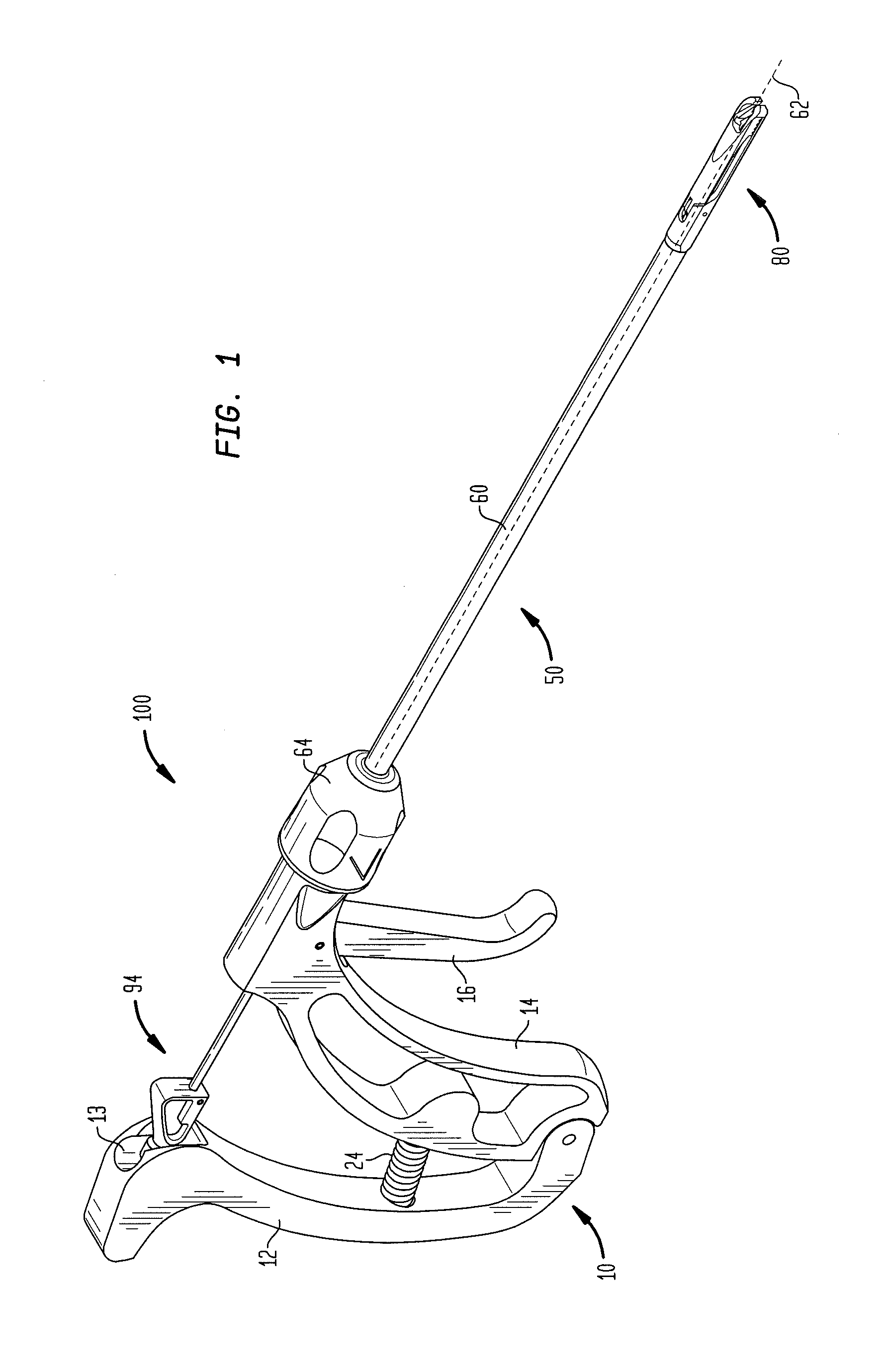
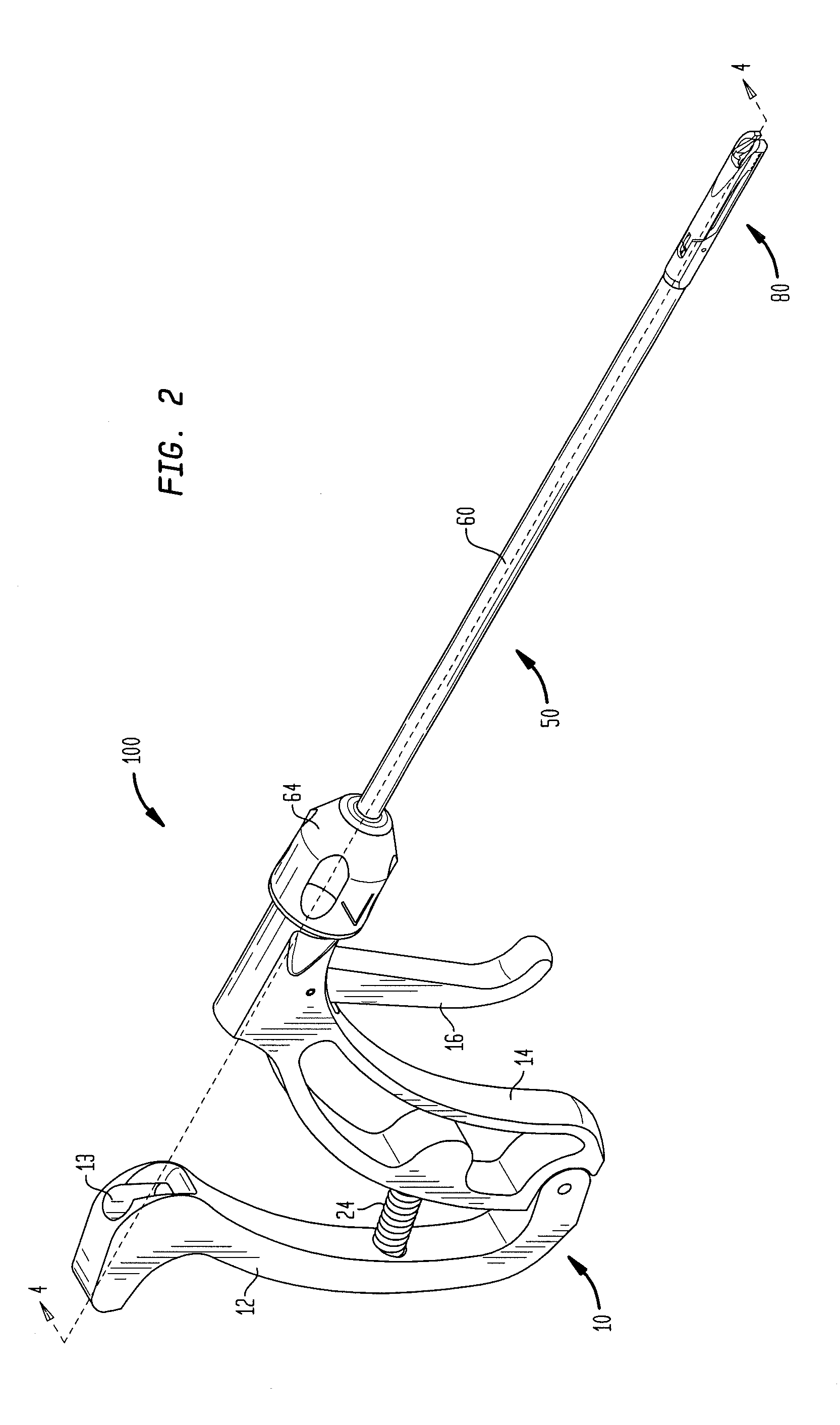
[0035]FIGS. 1-20 show a suture passer assembly 100 and components thereof, where assembly 100 includes a handle portion 10, a shaft portion 50, a jaw portion 80, and a needle assembly 94. Jaw portion 80 is depicted in a closed configuration in FIGS. 1-4 and in an open configuration in FIGS. 6, 8, and 9. Needle assembly 94 is adapted to be operated by handle portion 10, extend through shaft portion 50, and cooperate with jaw portion 80 to pass a suture through tissue. Shaft portion 50 is coupled to jaw portion 80, and as a unit, shaft portion 50 and jaw portion 80 are rotatably connected with handle portion 10. This allows shaft portion 50 and jaw portion 80 to be rotated with respect to handle portion 10, which rotation occurs about a central axis 62 (shown in FIG. 1) of a shaft 60 of shaft portion 50. Thus, a surgeon may ergonomically perform a suturing procedure by grasping and operating handle portion 10 from any number of locations about axis 62 that are independent of the posit...


PUM


Abstract

A surgical instrument and method of using same are provided. The instrument includes a jaw portion extending along an axis and a handle portion rotatably connected with the jaw portion and configured to at least partially rotate about the axis with respect to the jaw portion. A needle assembly can be configured to pass through the jaw portion and along the axis by cooperation with the handle portion. The jaw portion, or a shaft portion connecting the jaw portion and the handle portion, can include at least one spring-assisted bearing and the handle portion can include at least one depression configured to engage the at least one spring-assisted bearing in an orientation that temporarily locks the shaft portion with respect to handle portion. A method includes rotating the handle portion with respect to the jaw portion and actuating the instrument to pass a portion of a suture through tissue.

Description

CROSS-REFERENCE TO RELATED APPLICATIONS[0001]This application claims the benefit of the filing date of U.S. Provisional Patent Application No. 61 / 296,718 filed Jan. 20, 2010, the disclosure of which is hereby incorporated herein by reference.BACKGROUND OF TEE INVENTION[0002]The present invention relates to suture passer assemblies and methods of using same. More particularly, the present invention relates to a front-loading suture passer device having a distal end that is rotatable with respect to the handle.[0003]There are known surgical instruments that allow a surgeon to pass a suture through tissue, for example during an arthroscopic rotator cuff repair. Such instruments may include a tissue grasping portion such as a pair of jaws that allows for the tissue to be grasped while a piercing instrument punctures through the tissue. The procedures in which these instruments are used are often arthroscopic in nature, and are often performed through a cannula, which may only be placed ...

Claims


Application Information

Patent Timeline
Patent Type & Authority Applications(United States)
IPC IPC(8): A61B17/04
CPCA61B17/0469A61B17/0482A61B17/0483A61B2017/2926A61B17/0625A61B2017/06042A61B2017/2918A61B17/06061
Inventor WYMAN, JEFFREYYEARSLEY, RYAN E.BORCHERT, JEREMY DIRKSINNOTT, MARGARET MARY
Owner HOWMEDICA OSTEONICS CORP
Learn More