Trash receptacle vacuum release vent

a technology for trash receptacles and vents, which is applied in the field of trash receptacles, can solve the problems of requiring a person, unable to adapt to retrofitting an ordinary trash receptacle with a vacuum release mechanism, and the simple task of removing a trash bag from its receptacle is rendered difficult and awkward,

Inactive Publication Date: 2011-10-20
KASTNER DAVID
View PDF10 Cites 7 Cited by
  • Summary
  • Abstract
  • Description
  • Claims
  • Application Information

AI Technical Summary

Benefits of technology

[0010]The composite vent creates a vertical airway along the corner of side of the trash receptacle, such that air can enter at the top of the panel and flow down the sides of the receptacle and into the...

Problems solved by technology

Such resistance often compels a person to hold down the receptacle with one hand while lifting the liner bag with the other hand.
Consequently, the simple task of removing a trash bag from its receptacle is rendered difficult and awkward.
These receptacles with built-iv venting have the disadvantages of not being adaptable to retrofitting an ordinary trash receptacle with a vacuum release mechanism.
Moreover, integral vents and baffles inside a trash receptacle create spaces that are difficult to clean and afford potential paths by which vermin can gain access to the receptacle's interior.
Specially fabricated trash re...

Method used


Image

  • Trash receptacle vacuum release vent
  • Trash receptacle vacuum release vent
  • Trash receptacle vacuum release vent

Examples


Embodiment Construction

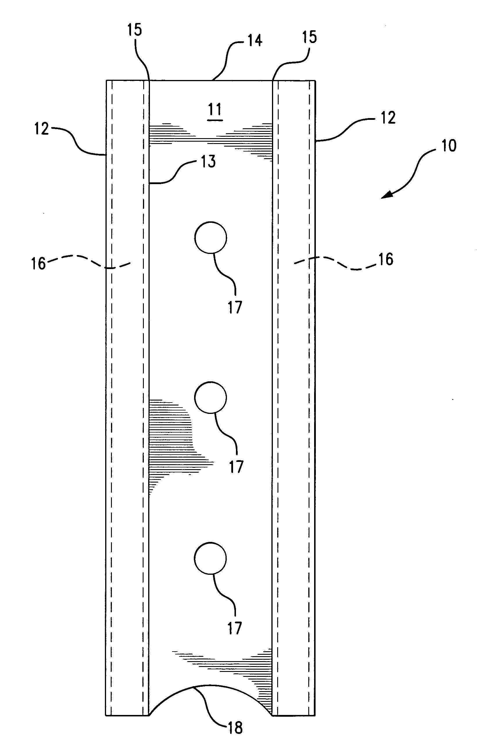
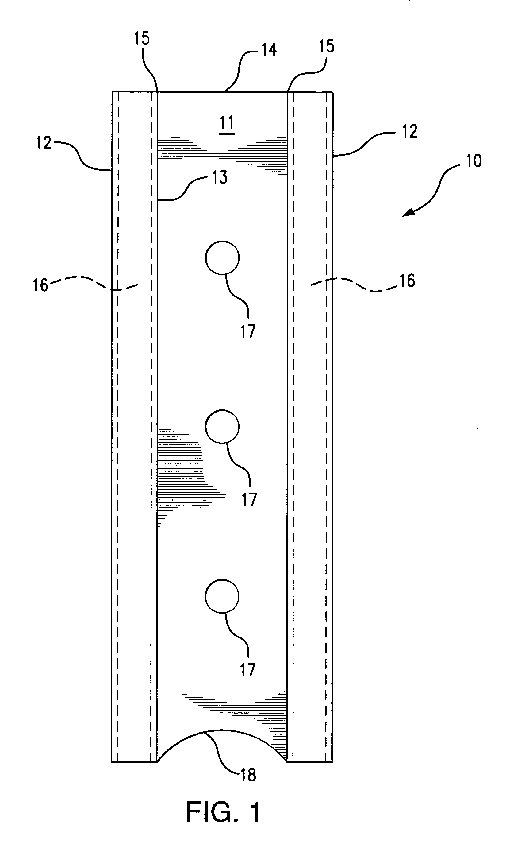
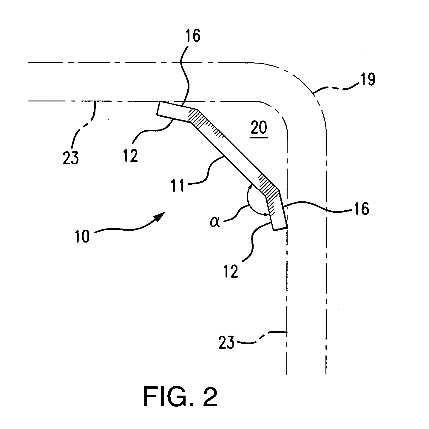
[0017]Referring to FIG. 1, the first embodiment of the present invention comprises a composite vent 10 having a central panel 11 to which are hingeably attached two side panels 12. The central panel 11 is rectangular in shape, with two elongated longitudinal sides 13 and two narrower lateral sides 14. Preferably, the length of the longitudinal sides 13 is in the range of 12 to 48 inches, corresponding to the height of the trash receptacle into which it will be inserted, while the width of the lateral sides 14 is in the range of 2 to 8 inches, depending on the size of the receptacle opening. The cross-section of the central panel 11 is preferably flat, but can be also be convex or concave, so as to better conform to the shape of the receptacle.

[0018]The two side panels 12 are hingeably attached along the two longitudinal sides 13 of the central panel 11. The length of the side panels 12 is equal to the length of the longitudinal sides 13 of the central panel 11, while the width of ea...


PUM


Abstract

A composite vent has an elongated rectangular central panel with two narrower longitudinal rectangular side panels hingeably attached or detachably connected thereto, such that the side panels form a range of obtuse angles with the central panel. The reverse sides of the side panels contain one or more adhesive strips, such that the vent can be securely attached across the corner or side of a trash receptacle regardless of the size or shape of the receptacle or the angle at which the side walls of the receptacle meet to form a corner. The composite vent creates a vertical airway along the corner of side of the trash receptacle, such that air can enter at the top of the panel and flow down the sides of the receptacle and into the bottom below the liner bag. To prevent obstruction of the airway by the liner, the vent panel can be perforated at intervals along its length, and/or it contain a vent opening at its lower edge.

Description

BACKGROUND OF THE INVENTION[0001]The current invention relates to the field of trash receptacles, and more particularly to trash receptacles that incorporate a means of releasing the vacuum typically created between the liner bag and the inner walls and bottom of the receptacle.[0002]Trash receptacles come in a variety of shapes and sizes and are commonly used in domestic, commercial and industrial applications. In order to avoid contamination of the interior of such receptacles, a plastically deformable liner bag is usually inserted into the receptacle, such that the liner covers the side walls and bottom of the receptacle and extends around the perimeter of the receptacle opening. As the liner bag is filled with trash, it is compressed against the sides and bottom of the receptacle. This compression forces the air out of the spaces between the liner and the interior of the receptacle, thereby creating a partial vacuum, which offers strong resistance to removal of the liner when th...

Claims


Application Information

Patent Timeline
IPC IPC(8): B65D25/14
CPCB65F1/068B65F1/06
Inventor KASTNER, DAVID
Owner KASTNER DAVID
Why Eureka
Try Eureka