
Tactile feedback method and system, computer program and storage medium that stores the computer program

a technology of tactile sensation and computer program, applied in the field of simulating tactile sensation, can solve the problems of limited types of tactile sensation that cannot be simulated, cannot be natural, and can only be simulated of limited kinds of objects, so as to achieve natural and realistic tactile sensation

Active Publication Date: 2011-10-20
PANASONIC CORP
View PDF6 Cites 45 Cited by
  • Summary
  • Abstract
  • Description
  • Claims
  • Application Information

AI Technical Summary

Benefits of technology

The present invention provides a system and method for simulating various tactile sensations that a person may feel when touching different objects. The system includes a removing section that removes a contact-device-specific oscillating waveform from a first contact-generated waveform, which represents a frictional vibration produced when a contact device contacts with one object. The first contact-generated waveform is then combined with a finger-pulp-specific oscillating waveform, which represents a frictional vibration produced when a person's finger pulp contacts with another object. The combined waveform is then used to create a vibration stimulation that can be displayed on a screen. The system can also include a computer program that performs the same steps as the system. Overall, the invention provides a way to simulate a variety of tactile sensations and provide a more realistic and immersive user experience.

Problems solved by technology

According to these conventional technologies, however, the tactile sensations of only limited kinds of objects can be simulated.
In addition, just limited types of tactile sensations can barely be simulated and far from being natural.
That is why according to such a method, if any other piece of information is required, the tactile sensation of the object cannot be simulated.
However, no model that can perfectly describe, for every possible combination of materials, what kind of frictional vibration will be produced when the two materials rub against each other has ever been discovered.
Likewise, sufficient knowledge has not been obtained yet as to what combination of firing patterns of the tactile receptors or what kind of vibration of the skin surface makes the person get a soft feel or a rough feel, for example.

Method used


Image

  • Tactile feedback method and system, computer program and storage medium that stores the computer program
  • Tactile feedback method and system, computer program and storage medium that stores the computer program
  • Tactile feedback method and system, computer program and storage medium that stores the computer program

Examples


embodiment 1

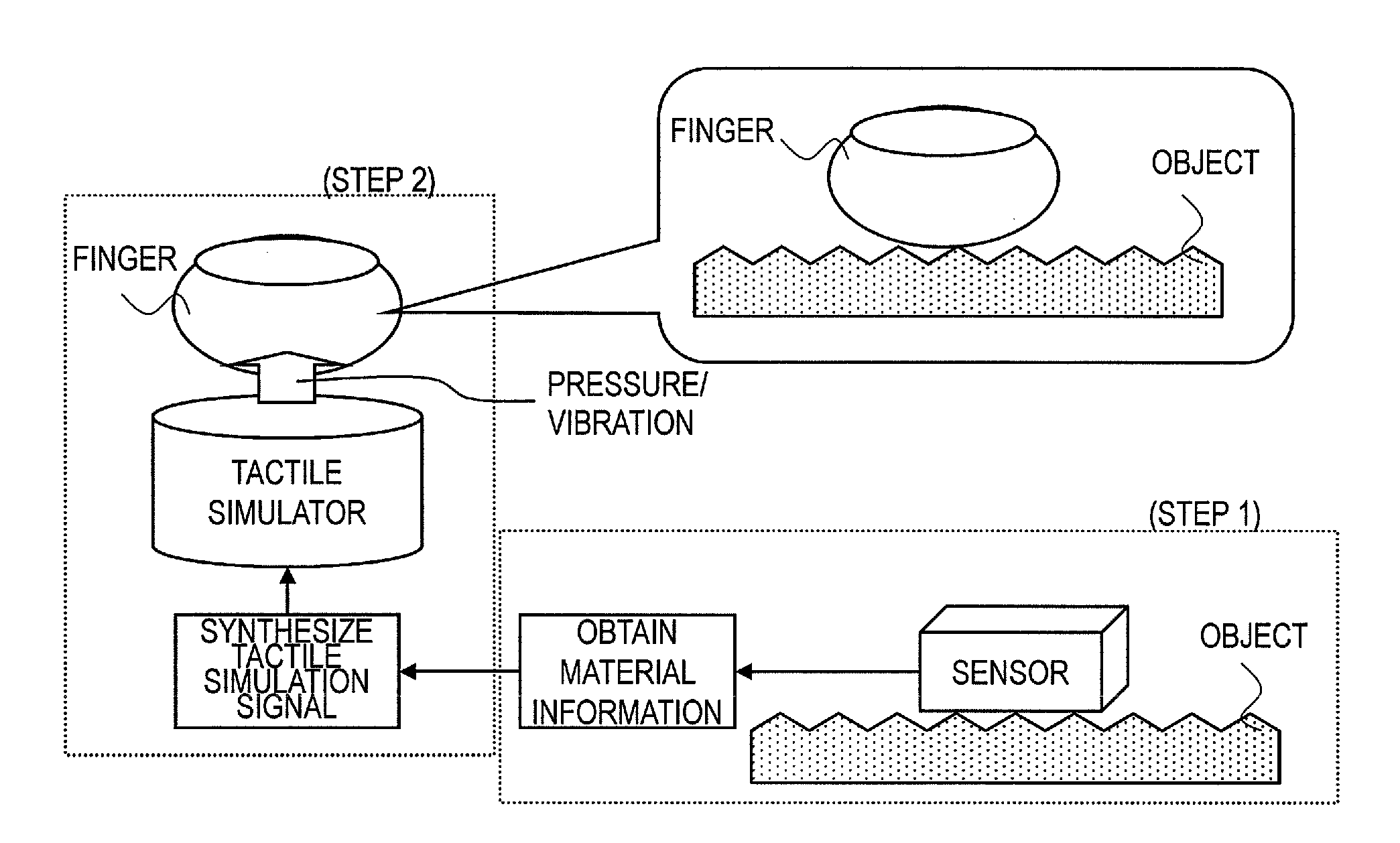
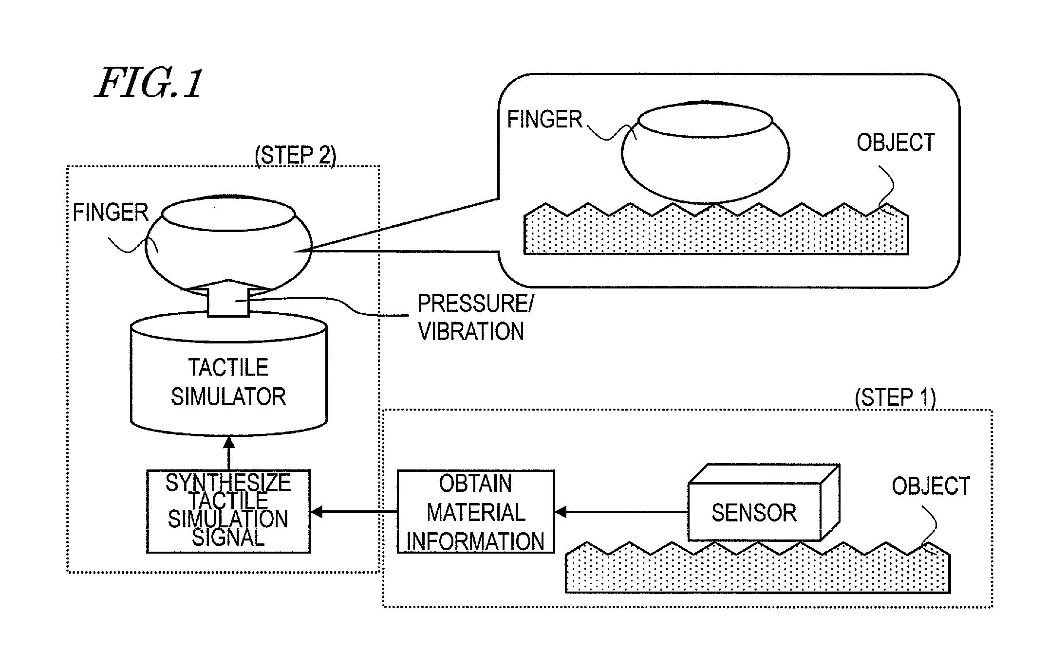
[0079]As a Method for Performing the Basic Function of the present invention, a signal conversion method and a frictional vibration generating method will be described as a first preferred embodiment of the present invention. According to this preferred embodiment, the patterns in which the contact produces frictional vibrations are learned in advance, thereby causing a realistic tactile sensation of any material on a person's finger pulp.

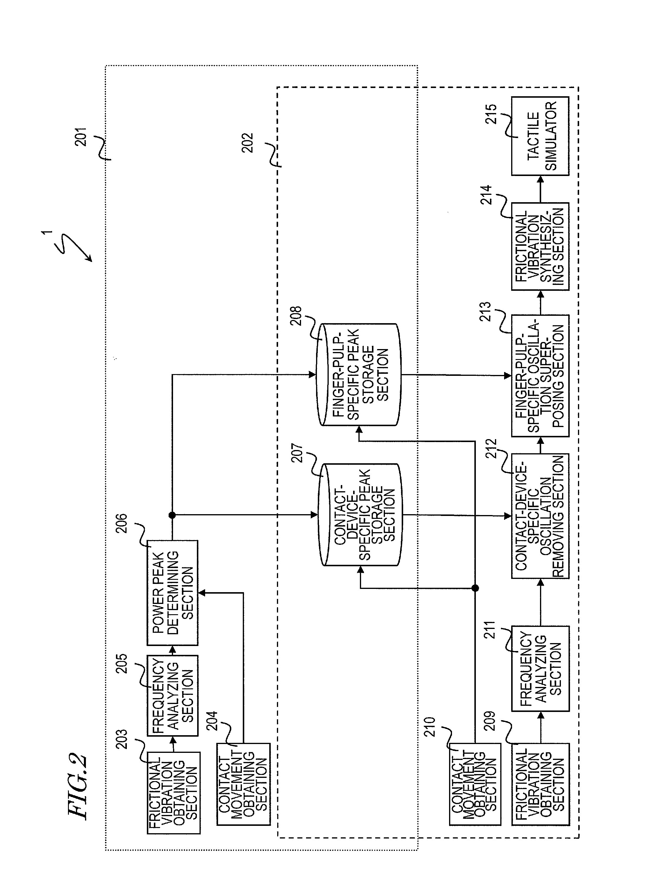
[0080]FIG. 2 is a block diagram illustrating a tactile feedback apparatus 1 as a first preferred embodiment of the present invention. This tactile feedback apparatus 1 has two major sections, which will be referred to herein as a power peak learning section 201 and a tactile feedback performing section 202, respectively.

[0081]In accordance with Equations (5) and (6) in which the frictional vibration produced by rubbing is supposed to be equivalent to the product of a signal source and a transfer system, the power peak learning section 201 determine...

embodiment 2

[0163]A tactile feedback apparatus as a second specific preferred embodiment of the present invention uses not only all of the basic components already described for the first preferred embodiment of the present invention but also multiple combinations of contact devices for getting a feel of the material and contact-device-specific peak information about those contact devices. Thus, the tactile feedback can be made by changing the contact devices or the contact-device-specific peak information to use according to the situation of the material, of which the feel should be simulated.

[0164]FIG. 15 is a block diagram illustrating a tactile feedback apparatus 2 as a second preferred embodiment of the present invention.

[0165]In FIG. 15, any component also included in the tactile feedback apparatus shown in FIG. 2 and having substantially the same function as its counterpart is identified by the same reference numeral and a detailed description thereof will be omitted herein. Just like th...

embodiment 3

[0177]A tactile feedback apparatus as a third specific preferred embodiment of the present invention not only uses all of the basic components already described for the first preferred embodiment of the present invention but also collects and stores multiple sets of finger-pulp-specific peak information for finger pulps with mutually different physical properties. And when a particular material feel should be displayed to a given finger pulp on the tactile simulator, the best one of the multiple sets of finger-pulp-specific peak information is used selectively for tactile feedback according to the property of the given finger pulp. As a result, it is possible to prevent the person from finding the tactile sensation caused on his or her finger pulp unnatural due to a disagreement in finger pulp property.

[0178]FIG. 17 is a block diagram illustrating a tactile feedback apparatus 3 as a third specific preferred embodiment of the present invention.

[0179]In FIG. 17, any component also inc...


PUM


Abstract

A tactile feedback system includes: a removing section for removing a contact-device-specific oscillating waveform, included in both a first contact-generated waveform representing a frictional vibration produced when a contact device contacts with one object and a second contact-generated waveform representing a frictional vibration produced when the contact device contacts with another object, from the first contact-generated waveform; a superposing section for superposing a finger-pulp-specific oscillating waveform, included in both the first finger-pulp-generated waveform representing a frictional vibration produced when a person's finger pulp contacts with the one object and the second finger-pulp-generated waveform representing a frictional vibration produced when the finger pulp contacts with that another object, on the first contact-generated waveform from which the contact-device-specific oscillating waveform has been removed; and a simulating section for displaying a vibration stimulation based on the first contact-generated waveform on which the finger-pulp-specific oscillating waveform has been superposed.

Description

[0001]This is a continuation of International Application No. PCT / JP2010 / 005338, with an international filing date of Aug. 30, 2010, which claims priority of Japanese Patent Application No. 2009-203542, filed on Sep. 3, 2009, the contents of which are hereby incorporated by reference.BACKGROUND OF THE INVENTION[0002]1. Field of the Invention[0003]The present invention relates to a technology for simulating a tactile sensation that a person would get when touching an object, and more particularly relates to a technology for simulating a tactile sensation to be gotten by him or her about the material or shape of that object.[0004]2. Description of the Related Art[0005]Recently, thanks to development of audiovisual technologies and network technologies and expansion of their infrastructures, video (visual information) and audio (audio information) can now be transmitted to any distant location with a rather high degree of reality. But there should be ever-increasing demands in the near...

Claims


Application Information

Patent Timeline
Patent Type & Authority Applications(United States)
IPC IPC(8): G08B6/00
CPCG06F3/016
Inventor OKIMOTO, YOSHIYUKIMOTOMURA, HIDETO
Owner PANASONIC CORP
Learn More