Forehead support for a patient interface

a patient interface and support technology, applied in the field of patient interfaces, can solve problems such as pressure sores on the fa

Active Publication Date: 2011-10-27
RESMED LTD
View PDF12 Cites 91 Cited by
  • Summary
  • Abstract
  • Description
  • Claims
  • Application Information

AI Technical Summary

Problems solved by technology

This can lead to pressure sores on their face.
It is a continuing challenge for designers and manufacturers to provide a patient interface with comfortable seal against leak.

Method used


Image

  • Forehead support for a patient interface
  • Forehead support for a patient interface
  • Forehead support for a patient interface

Examples


Embodiment Construction

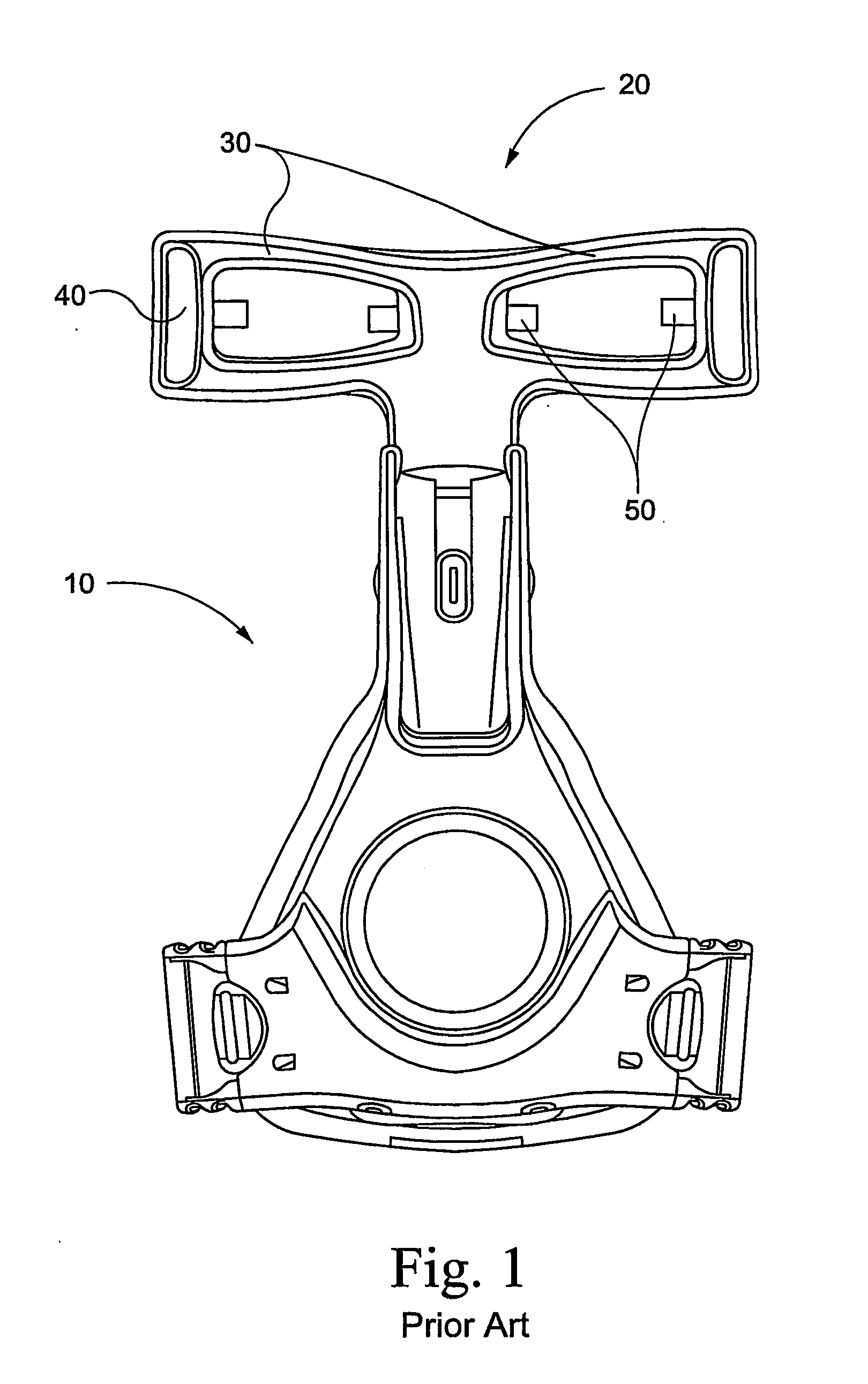
[0024]A prior art mask assembly 10 such as ResMed's ULTRA MIRAGE® mask as shown in FIG. 1 includes a forehead support 20 having a pair of arms 30, each having a slot 40 adapted to receive a strap (not shown). Each arm 30 includes a pair of forehead pad receiving lugs 50. The forehead support has a general “T”-shape, with the arms arranged along the upper cross portion of the “T”:

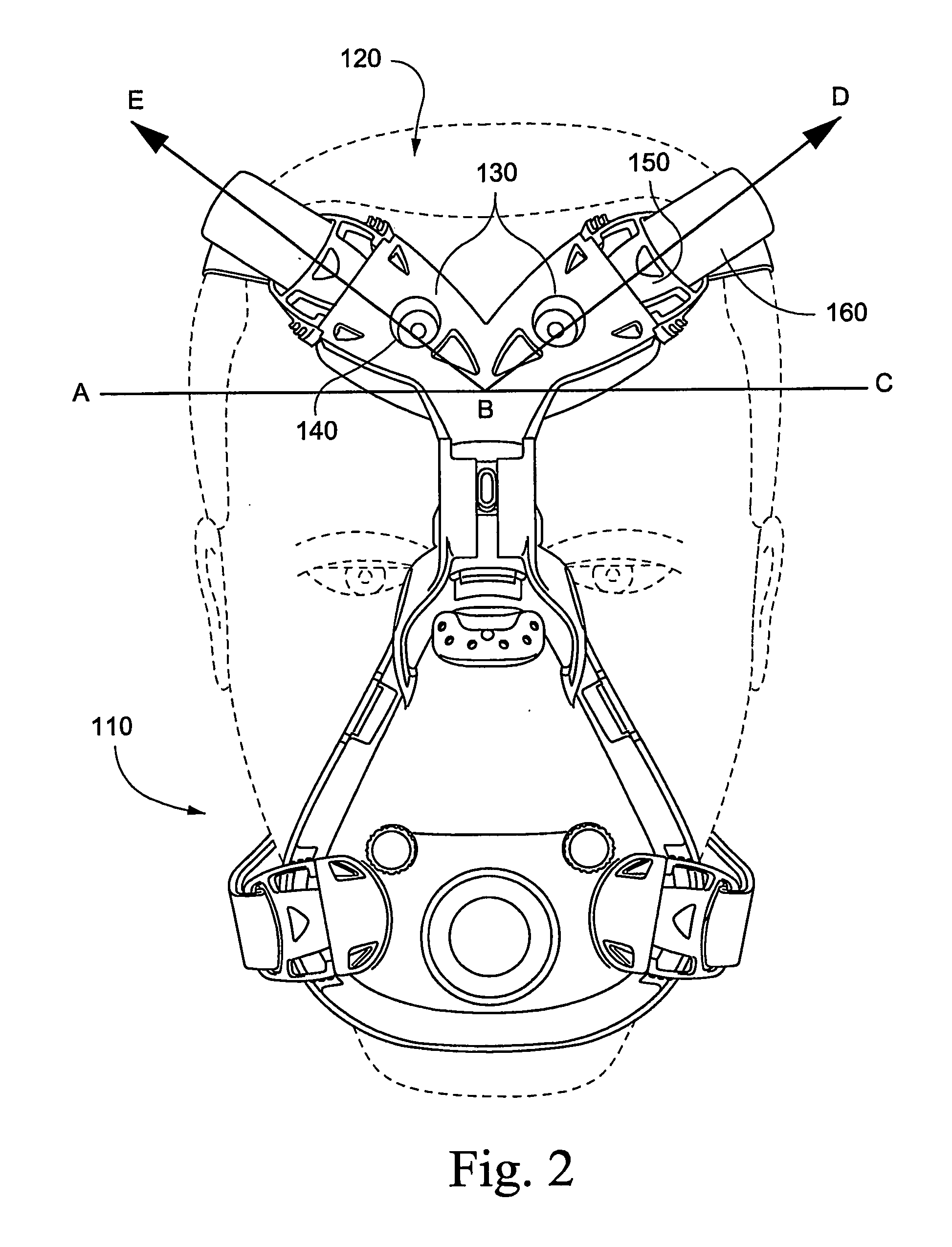
[0025]As shown in FIG. 2, a mask assembly 110 in accordance with a first aspect of the invention provides a forehead support 120 including a pair of arms 130 defining an included angle EBD of less than 180°, for example 100°-150°, preferably 120°. Thus the forehead support is generally “Y”-shaped. In the embodiment shown in FIG. 2, each arm includes a slot arrangement 140 adapted to receive a forehead support clip 150. Each forehead support clip 150 is in turn adapted to engage with a forehead support strap 160. There is a line of force BE and BD for the respective arms 130.

[0026]Each arm 130 is disposed at ...


PUM


Abstract

Mask assembly (110, 300, 400, 500) includes a forehead support (120, 220, 316, 416, 520) having a base provided to a frame and two upwardly extending support arms (130, 230, 318, 418, 518). The arms define a fixed or adjustable included angle that is less than 180 degrees and in the range of about 100-150 degrees. The arms can be attached either directly to headgear straps, or the arms can be connected to headgear straps via clips (150, 506). Also claimed is an embodiment with one arm.

Description

CROSS-REFERENCE TO APPLICATIONS[0001]This application claims the benefit of U.S. Provisional Application No. 60 / 582,538, filed Jun. 25, 2004, which is incorporated herein by reference in its entirety.FIELD OF THE INVENTION[0002]The invention relates to a patient interface used for treating sleep disordered breathing. In particular, the invention relates to a forehead support for a patient interface.BACKGROUND OF THE INVENTION[0003]In the treatment of sleep disordered breathing, a patient receives a supply of air or breathable gas at positive pressure to “splint” open their airway. The supply of air or gas is delivered to the patient via a patient interface, such as a facial mask. The patient interface is typically held in position by headgear. Headgear typically includes a number of straps that in use are attached to the patient interface at an anchor point. In use, the various straps are tightened to secure the mask in position and to prevent it from lifting off the face under pres...

Claims


Application Information

Patent Timeline
Patent Type & Authority Applications(United States)
IPC IPC(8): A61M16/04
CPCA61M16/06A61M16/0683A61M16/0816A61M16/0638A61M16/0655A61M16/0057A61M16/0875A61M16/065A61M16/0694A62B18/025A62B18/084
Inventor HITCHCOCK, ROBIN GARTHWORBOYS, DAVID JOHND'SOUZA, ERROL SAVIO ALEX
Owner RESMED LTD
Why Eureka
Try Eureka