Convertible infant rocker
- Summary
- Abstract
- Description
- Claims
- Application Information
AI Technical Summary
Benefits of technology
Problems solved by technology
Method used
Image
Examples
first embodiment
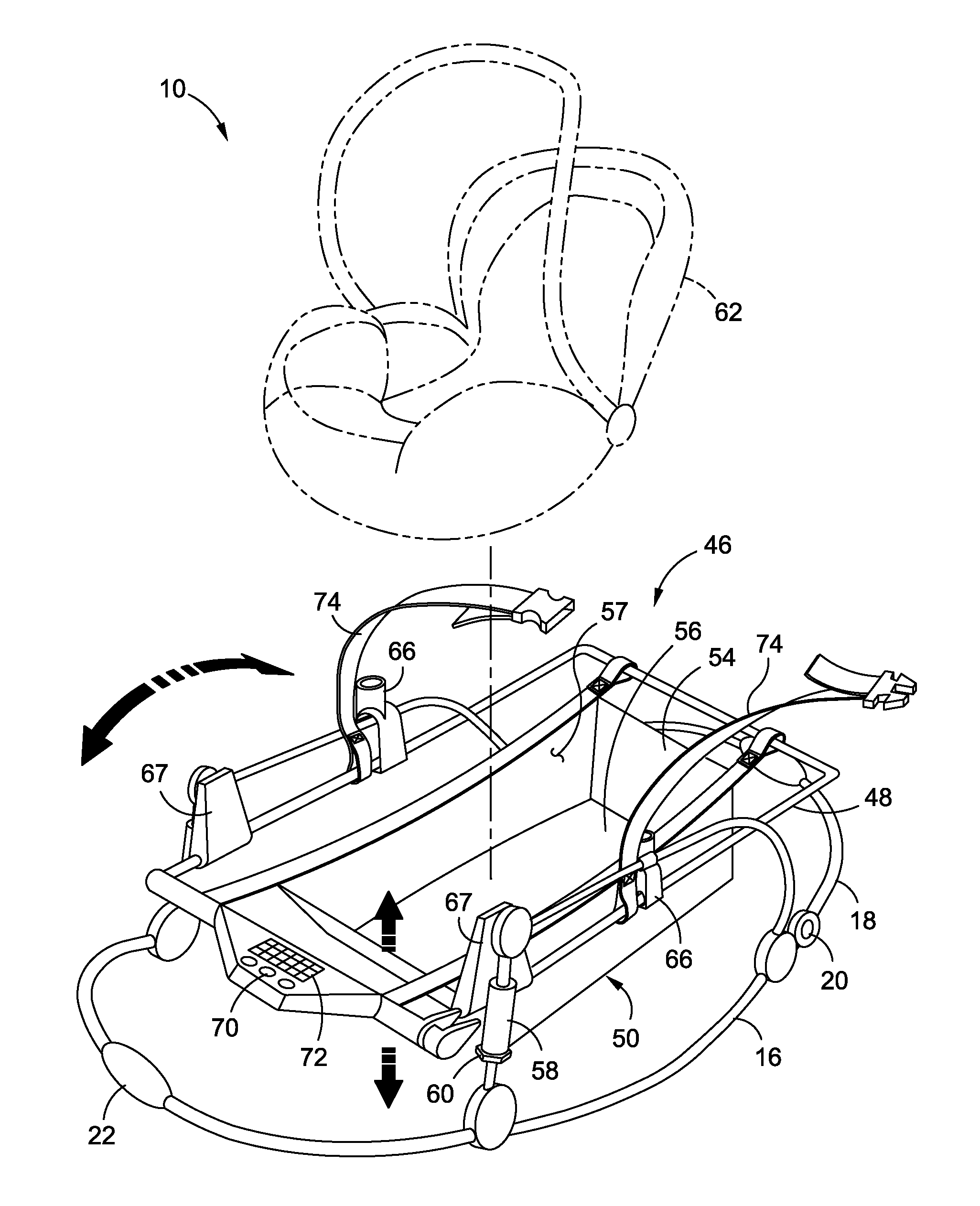
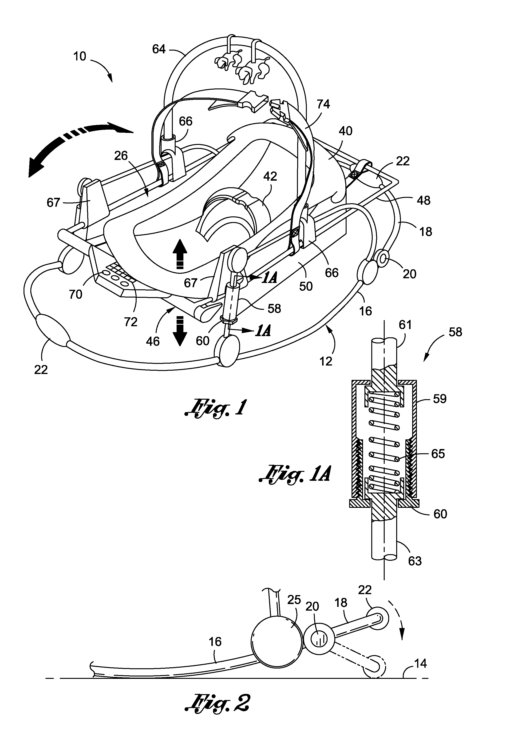
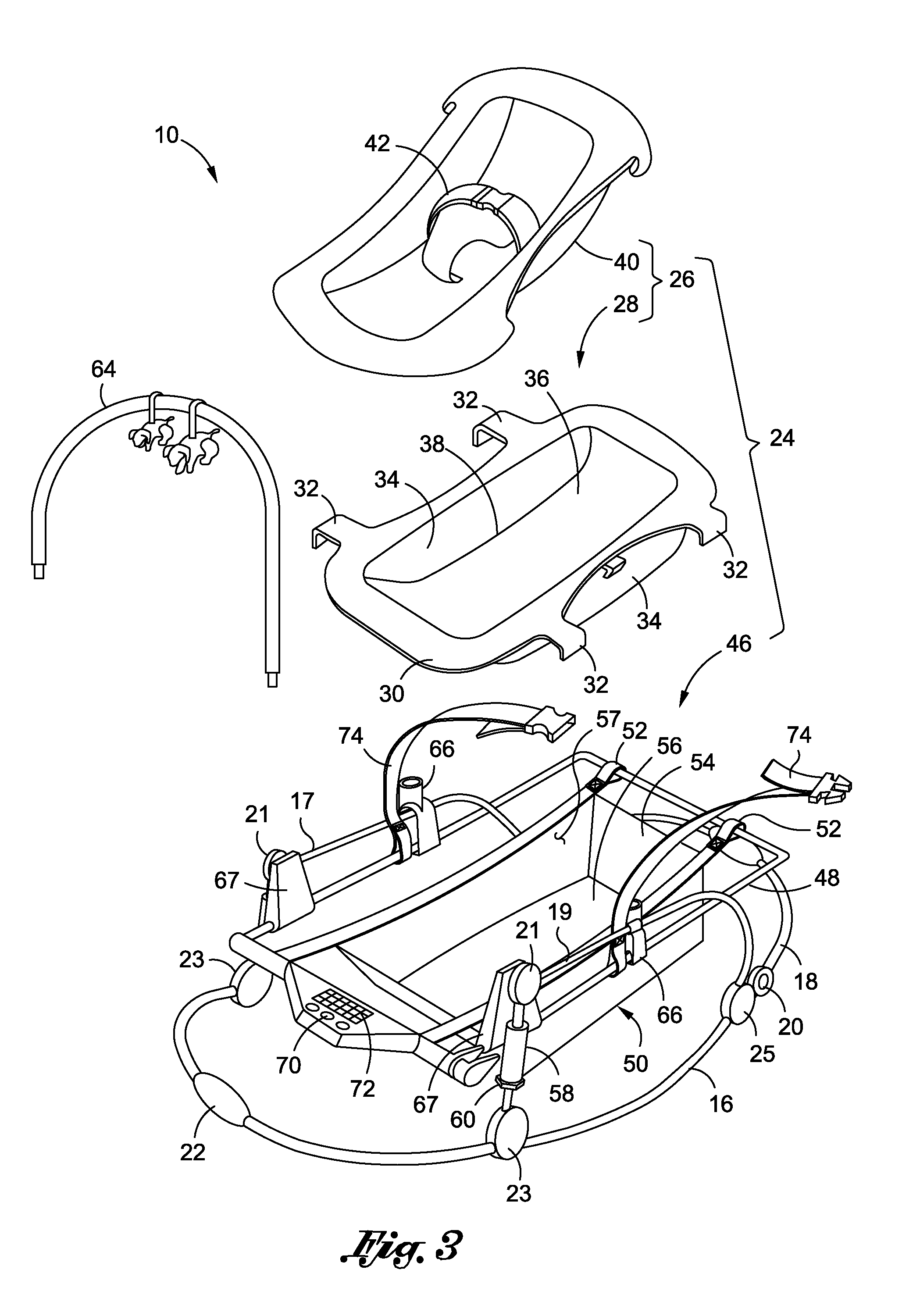
[0028]Referring now to the drawings wherein the showings are for purposes of illustrating various embodiments of the present invention only, and not for purposes of limiting the same, FIGS. 1-4 depict a convertible infant rocker 10 constructed in accordance with the present invention. As will be discussed in more detail below, the rocker 10 includes a bounce adjustment mechanism which may be selectively adjusted to alter or vary the magnitude of bounce or vibration within the frame of the rocker 10 which may be achieved by an infant or child disposed therein. As a result, the bounce adjustment mechanism may be adjusted to accommodate children of varying weight. As will also be described in more detail below, it is contemplated that the rocker 10 may be converted into a mode which allows the same to be used in conjunction with a conventional infant / child car seat 62.
[0029]Referring specifically to FIG. 1, the rocker 10 comprises a frame 12 which is selectively placeable on an underly...
third embodiment
[0056]Referring now to FIGS. 8-12, there is shown a convertible infant rocker 210 constructed in accordance with the present invention. As will be discussed in more detail below, the infant rocker 210, in addition to being convertible between the liner and car seat modes as described above in relation to the rockers 10, 110, is further configured to be quickly and easily collapsible for storing the infant rocker 210 during periods of nonuse.
[0057]The infant rocker 210 comprises a frame 212 which is selectively placeable on an underlying support surface. The frame 212 includes a generally U-shaped lower section 216 which is bent to assume a generally arcuate profile as most easily seen in FIG. 9. Attached to respective ones of the opposed end portions of the lower section 216 is an identically configured pair of end connectors 218. As best seen in FIG. 8, each of the end connectors 218 is outfitted with a non-slip pad 219 which is preferably fabricated from rubber and, when viewed fr...
PUM
 Abstract
Description
Claims
Application Information
 - R&D
- Intellectual Property
- Life Sciences
- Materials
- Tech Scout
- Unparalleled Data Quality
- Higher Quality Content
- 60% Fewer Hallucinations
Browse by: Latest US Patents, China's latest patents, Technical Efficacy Thesaurus, Application Domain, Technology Topic, Popular Technical Reports.
© 2025 PatSnap. All rights reserved.Legal|Privacy policy|Modern Slavery Act Transparency Statement|Sitemap|About US| Contact US: help@patsnap.com


