Method and a system for monitoring vibratory phenomena that occur in an aviation gas turbine engine in operation

a technology of vibratory phenomena and gas turbine engines, which is applied in the field of monitoring gas turbine engines, can solve the problems of not always guaranteed, complicated or even impossible to calculate the theoretical operating frequency with defects for all components of the engine, and the prior art monitoring method presents certain limits as to its application, so as to achieve the effect of reducing such drawbacks and improving the monitoring of the aircraft gas turbine engin

Active Publication Date: 2011-11-10
SN DETUDE & DE CONSTR DE MOTEURS DAVIATION S N E C M A
View PDF4 Cites 8 Cited by
  • Summary
  • Abstract
  • Description
  • Claims
  • Application Information

AI Technical Summary

Benefits of technology

[0006]A main object of the present invention is thus to mitigate such drawbacks by proposing a method and a system enabling the monitoring of an aircraft gas turbine engine to be improved.
[0014]Having recourse to particular mathematical functions for defining vibratory signatures makes it possible to cover all of the vibratory phenomena that occur in the engine and that originate from a defect in or abnormal operation of a component of the engine, regardless of whether the phenomena are organized or not, or are theoretically predictable or not. As a result, all defects in and abnormal operation of components of the engine that give rise to particular vibratory phenomena in flight can be monitored. This makes it possible to improve monitoring of the engine.
[0015]According to an advantageous provision of the invention, the method further consists in generating a maintenance notice for the engine when the same message has been emitted repeatedly over a plurality of flights, over a plurality of identical flight stages, or over a plurality of periods of the engine operating at the same speed. This provision makes it possible to track variation in the particular vibratory phenomenon over time and to prevent damage to the engine by issuing a maintenance notice before damages occurs. This greatly improves maintenance operations and the potential for repairing the component in question from which the particular vibratory signature originates.
[0017]According to another advantageous provision of the invention, the mathematical functions defining the vibratory signatures are stored in a database that is capable of being updated. The use of such a database makes it possible, where necessary, to update the coefficients of the mathematical functions associated with the vibratory signatures, and to add new functions. In particular, this updating operation may be performed directly after a flight by making a connection to the database. Thus, the method presents great flexibility in use and of adaptation.

Problems solved by technology

Although effective, that type of prior art monitoring method nevertheless presents certain limits as to its application.
It is very complicated or even impossible to calculate the theoretical operating frequency with defects for all of the components of an engine.
And even if that is possible for some components, such calculation remains a simulation and is therefore of reliability that is not always guaranteed.
As a result, numerous vibratory phenomena occur in the engine during a flight of the aircraft that originate from an engine component defect but that are not detected or that are poorly interpreted, thereby running the risk of the corresponding consequences in terms of potential damage to the engine.
Furthermore, prior art monitoring methods do not make it possible to detect abnormal operation of a component of the engine, such as for example slip of a rolling element of a bearing in the raceways of the bearing.
Unfortunately, such abnormal operation, which is not necessarily associated with structural defects of the components of the engine, can give rise to damage to those components.

Method used


Image

  • Method and a system for monitoring vibratory phenomena that occur in an aviation gas turbine engine in operation
  • Method and a system for monitoring vibratory phenomena that occur in an aviation gas turbine engine in operation
  • Method and a system for monitoring vibratory phenomena that occur in an aviation gas turbine engine in operation

Examples


Embodiment Construction

[0033]The monitoring method and system of the invention apply to any type of gas turbine engine fitted to aircraft, such as airplanes or helicopters, for example.

[0034]In the presently-described example, attention is given more particularly to an airplane gas turbine engine that has two rotors. Naturally, the invention is not limited to a two-rotor engine but applies to any aircraft gas turbine engine having one or more rotors.

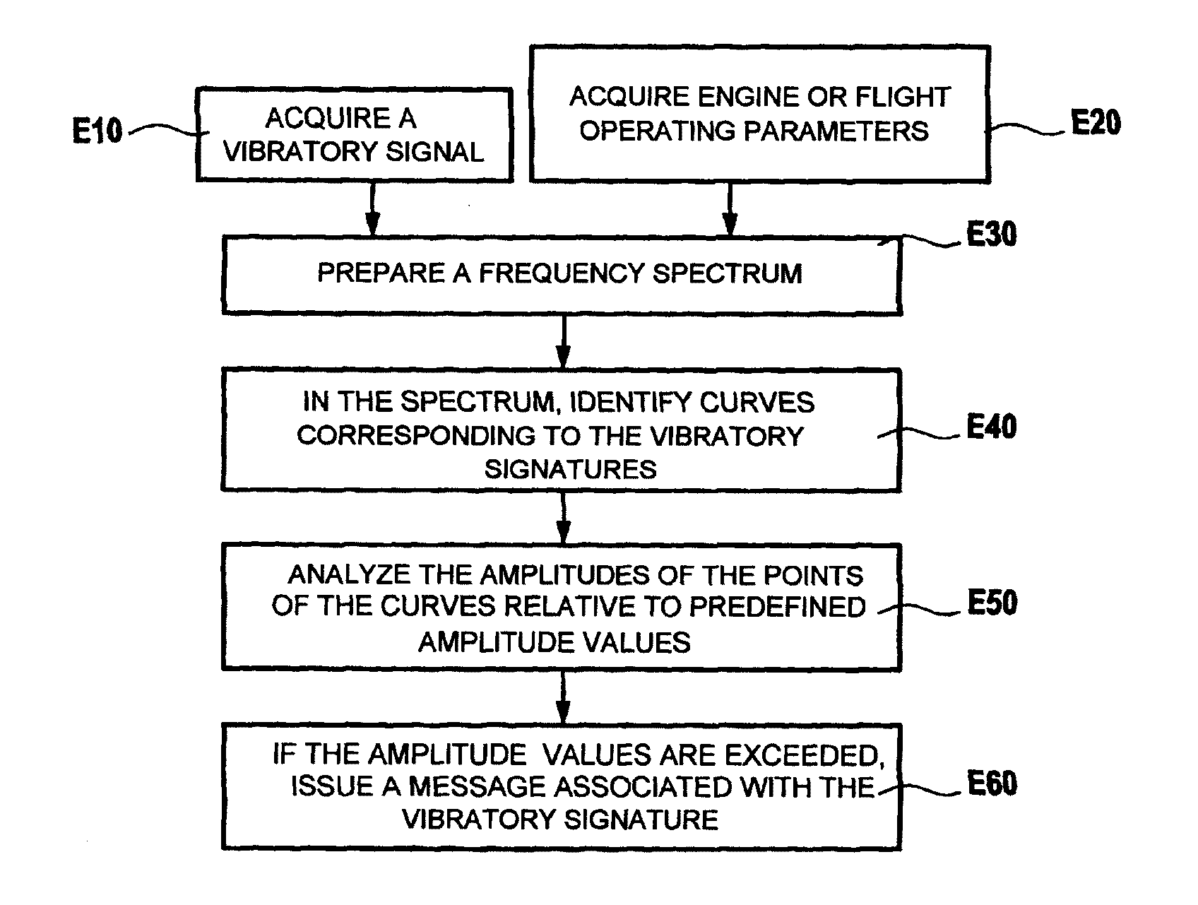
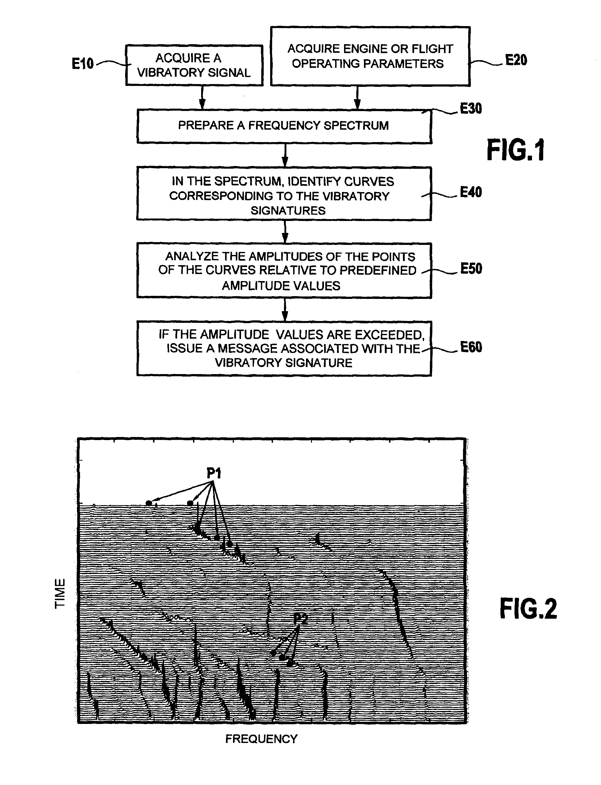
[0035]The monitoring method and system of the invention serves automatically to identify particular vibratory phenomena that occur in the engine in operation and that originate from a defect in or abnormal operation of a component in the engine (including ancillary equipment). The monitored defects comprise for example wear of a rolling element of a bearing, flutter of the fan (in a turbomachine), etc. As for abnormal operation of a component of the engine, this may involve, for example, a rolling element of a bearing sliding in its raceways.

[0036]The monitori...


PUM


Abstract

The invention relates to a method and a system for monitoring vibratory phenomena that occur in an aviation gas turbine engine in operation. The method consists: in establishing (E30) a frequency spectrum of a vibratory signal representative of the operating state of the engine and of its components; in using a plurality of vibratory signatures, each corresponding to a vibratory phenomenon that occurs during operation of aeroengines of the same type as the engine being monitored and originating from a defect in or an abnormal operation of a component of the engines; in identifying (E40), in the spectrum, the points of curves that match mathematical functions, each defining a vibratory signature; and for each identified curve corresponding to a defect of engine components, in analyzing (E50) the amplitude associated with the points of the curve relative to predefined amplitude values corresponding to a degree of severity of the defect; and as a result of an amplitude value being exceeded or an abnormal operation being detected, in issuing (E60) a message associated with the vibratory signature.

Description

BACKGROUND OF THE INVENTION[0001]The present invention relates to the general field of monitoring gas turbine engines of aircrafts, such as airplanes or helicopters, for example. The invention relates more particularly to a method and a system for monitoring vibratory phenomena that occur in an aircraft gas turbine engine while it is in operation.[0002]It is known to place accelerometer type vibration sensors in an aircraft engine in order to detect the vibration emitted by one or more particular components of the engine while the engine is in operation. The collected vibratory signal is analyzed in order to compare its amplitude with defined threshold values, each corresponding to operation with a defect of a particular monitored component. Thus, in the event of a defect in a monitored component of the engine, its operation causes a particular vibratory phenomenon to appear, which phenomenon may be detected by analyzing the vibratory signal.[0003]Document EP 1 970 691 describes suc...

Claims


Application Information

Patent Timeline
Patent Type & Authority Applications(United States)
IPC IPC(8): F02C7/00
CPCF02C9/28G01H1/00G01M13/028F05D2270/708G01M15/14F05D2260/96F05D2270/114G01M15/12
Inventor CARRATT, BRUNOFLORES, DAVIDJADCZAK, EDOUARD
Owner SN DETUDE & DE CONSTR DE MOTEURS DAVIATION S N E C M A
Why Eureka
Try Eureka