Electric wire connector for press connecting electric wires

Active Publication Date: 2011-11-24
JOWOO TECH
View PDF3 Cites 8 Cited by
  • Summary
  • Abstract
  • Description
  • Claims
  • Application Information

AI Technical Summary

Benefits of technology

[0007]Therefore, the present invention has been made in view of the above problems, and it is an object of the present invention to provide an electric wire connector that is capable of rapidly and easily connecting a plurality of electric wires to each other without using a special tool and without peeling off sheaths of the respective electric wires.

Problems solved by technology

Furthermore, the connection operation is complicated and troublesome.
In addition, safety against electric shock is not guaranteed.

Method used


Image

  • Electric wire connector for press connecting electric wires
  • Electric wire connector for press connecting electric wires
  • Electric wire connector for press connecting electric wires

Examples


Embodiment Construction

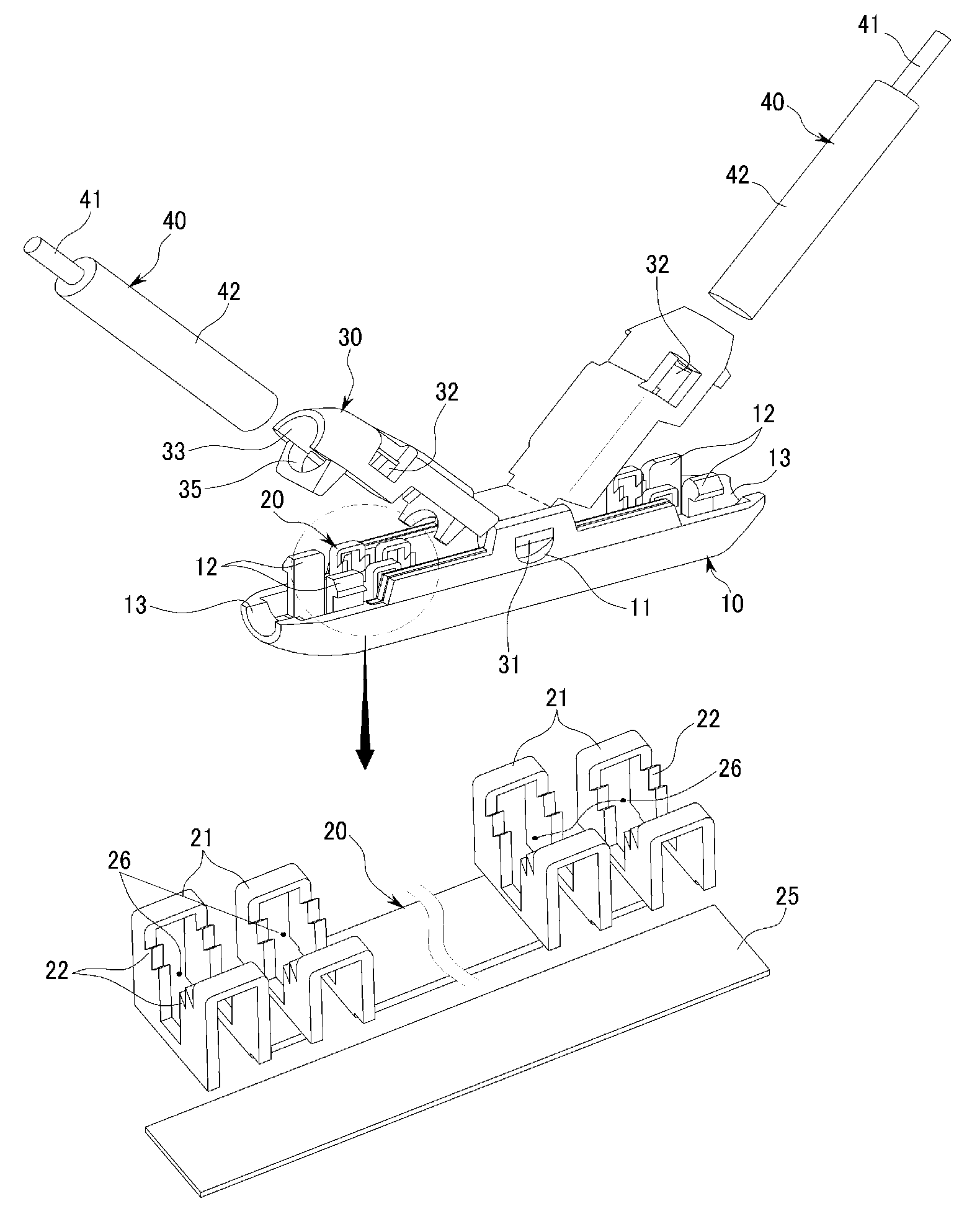
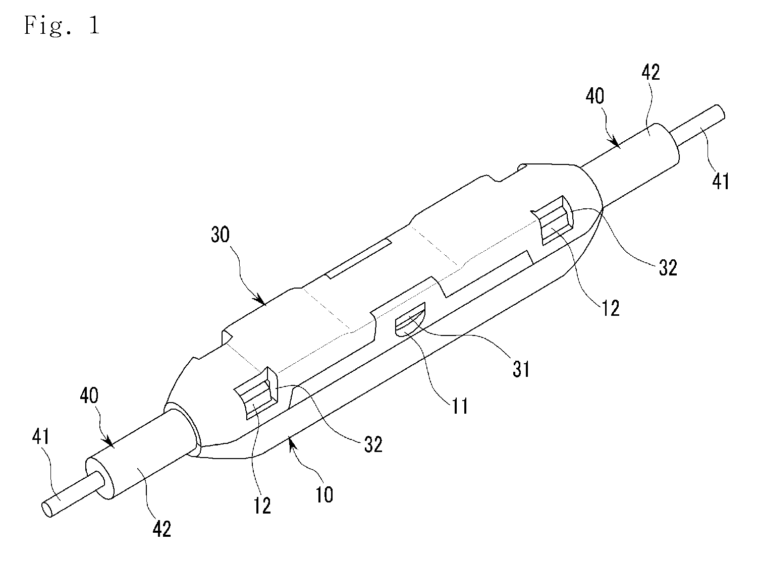
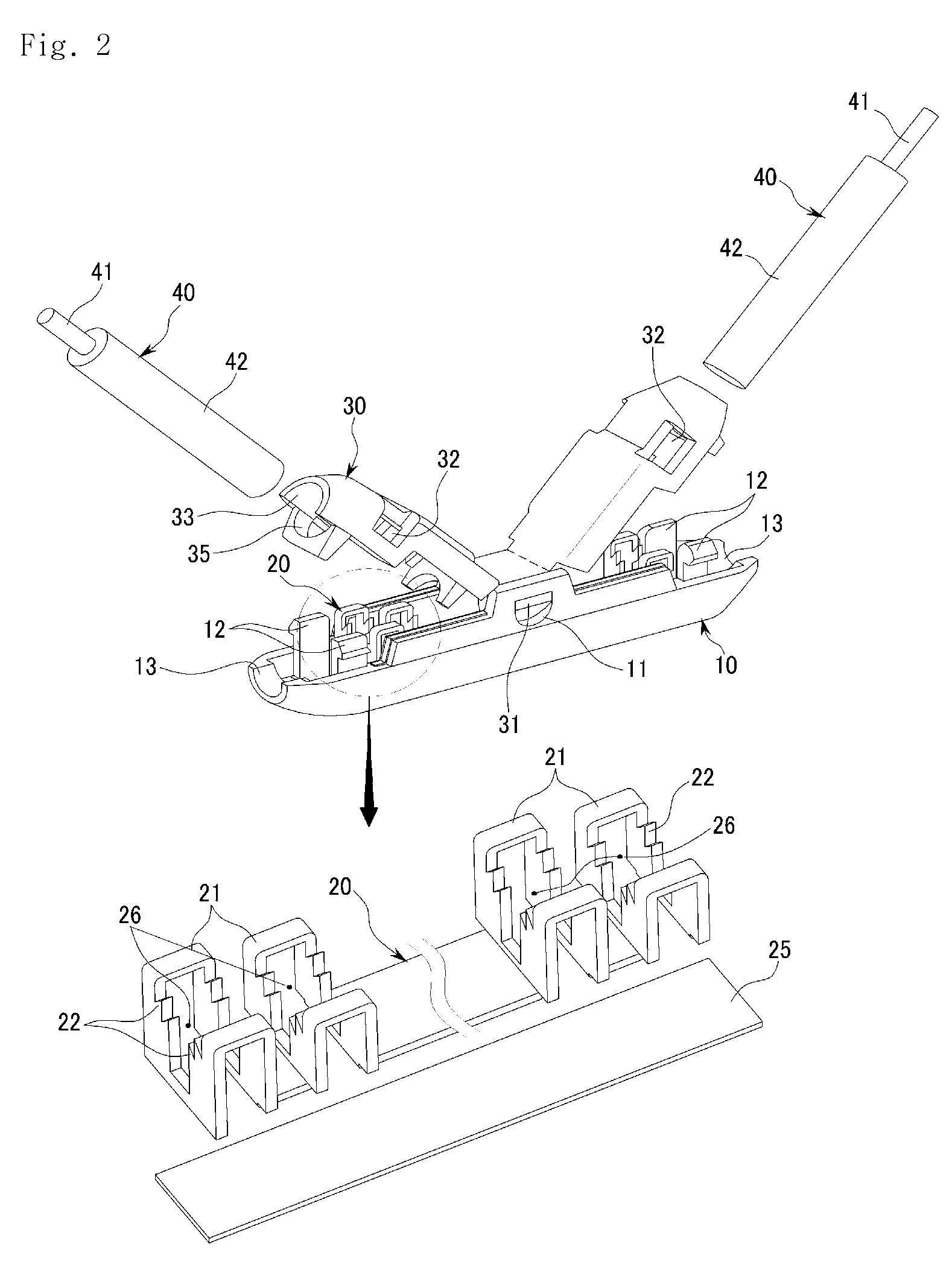
[0015]Now, preferred embodiments of the present invention will be described in detail with reference to the accompanying drawings such that the embodiments can be easily implemented by a person having ordinary skill in the art to which the invention pertains. However, the present invention may be implemented in various different forms, and therefore, the present invention is not limited to embodiments which will be described hereinafter. Also, parts having no connection with the present invention will be omitted from the drawings in order to more clearly describe the prevent invention, and similar reference numerals will be used throughout the specification to refer to similar parts.

[0016]Throughout the specification, when it is said that a certain part “includes” a certain element, this means that the part may further include other elements, not excluding them, unless otherwise mentioned.

[0017]An electric wire connector according to the present invention is formed by assembling an ...


PUM


Abstract

An electric wire connector includes an insulative lower connector formed in a shape extending in a first direction, the lower connector being open at a top thereof, the lower connector being provided at sides thereof with a plurality of fixing protrusions and shaft openings, an insulative upper connector formed in a shape extending in the first direction, the upper connector being open at a bottom thereof, the upper connector being provided at sides thereof with fixing holes into which the fixing protrusions of the lower connector are inserted and a fixing shaft inserted through the shaft openings of the lower connector, and a conductive member disposed in the lower connector, the conductive member having a plurality of cutting blades for peeling off sheaths of electric wires, the cutting blades being electrically connected to cores of the electric wires.

Description

CROSS REFERENCE TO THE RELATED APPLICATION [0001]This application is being filed as a continuation-in-part of Ser. No. 12 / 662,058 entitled electric wire connector, which was filed on Mar. 17, 2010.BACKGROUND OF THE INVENTION [0002]1. Field of the Invention[0003]The present invention relates to an electric wire connector, and, more particularly, to an electric wire connector that is capable of connecting electric wires to each other without peeling off sheaths of the respective electric wires.[0004]2. Description of the Related Art[0005]Connection between two or more separate electric wires may be achieved using a method of peeling sheaths of the electric wires, connecting exposed cores of the electric wires, and wrapping the connected cores with an insulating tape.[0006]In the method using insulating tape, however, a tool for twisting the cores of the electric wires is needed. Furthermore, the connection operation is complicated and troublesome. In addition, safety against electric ...

Claims


Application Information

Patent Timeline
IPC IPC(8): H01R4/24
CPCH01R4/2433
Inventor LEE, YOUNGHWAN
Owner JOWOO TECH
Why Eureka
Try Eureka