Swimming pools for courtyards, gardens or free spaces in dwellings

a technology for swimming pools and courtyards, applied in gymnasiums, buildings, construction, etc., can solve the problems of occupying too much space to be commercialized, employing external hoses and pumps, etc., and achieves the effect of quick and easy connection of outlet hoses

Inactive Publication Date: 2002-05-21
MUSSA EDUARDO ALBERTO
View PDF4 Cites 10 Cited by
  • Summary
  • Abstract
  • Description
  • Claims
  • Application Information

AI Technical Summary

Benefits of technology

are to provide a means whereby, once the structure of the swimming pool has been erected, the walls (i.e., of the frame and the membrane) provide improved support for the pool and the contents and means of rapidly and easily connecting an outlet hose to the pool.
Another object of the proposed invention is to provide a system for rapidly and easily coupling the water outlet hose. The described coupling means is in the form of a piece of plastic material which is integrally incorporated into one of the lateral walls of the swimming pool and which has an articulated plug which allows one to empty the swimming pool easily and quickly, through a large outlet flow aperature.
Finally, the present invention provides a dismountable swimming pool of low cost, which is achieved by way of a lesser number of tubular pieces, enabling easier and less expensive packaging of the product for sale, and facilitating compact storage during cold periods.
FIG. 3 is a cross sectional elevation view of the device which is integrally fixed to the wall of the swimming pool to enable easy and quick coupling of an outlet hose.

Problems solved by technology

Whereas the tubular structures utilized heretofore do indeed satisfy the principle purpose intended, they have the drawback that, being comprised of a plurality of tube segments which form the upper and lower frame substructures, they occupy too much space to be commercialized, and are costly due to the large number of pieces of which they are comprised.
Another drawback of the known structures is that in order to empty them one must employ an external hose and a pump.

Method used


Image

  • Swimming pools for courtyards, gardens or free spaces in dwellings
  • Swimming pools for courtyards, gardens or free spaces in dwellings
  • Swimming pools for courtyards, gardens or free spaces in dwellings

Examples


Embodiment Construction

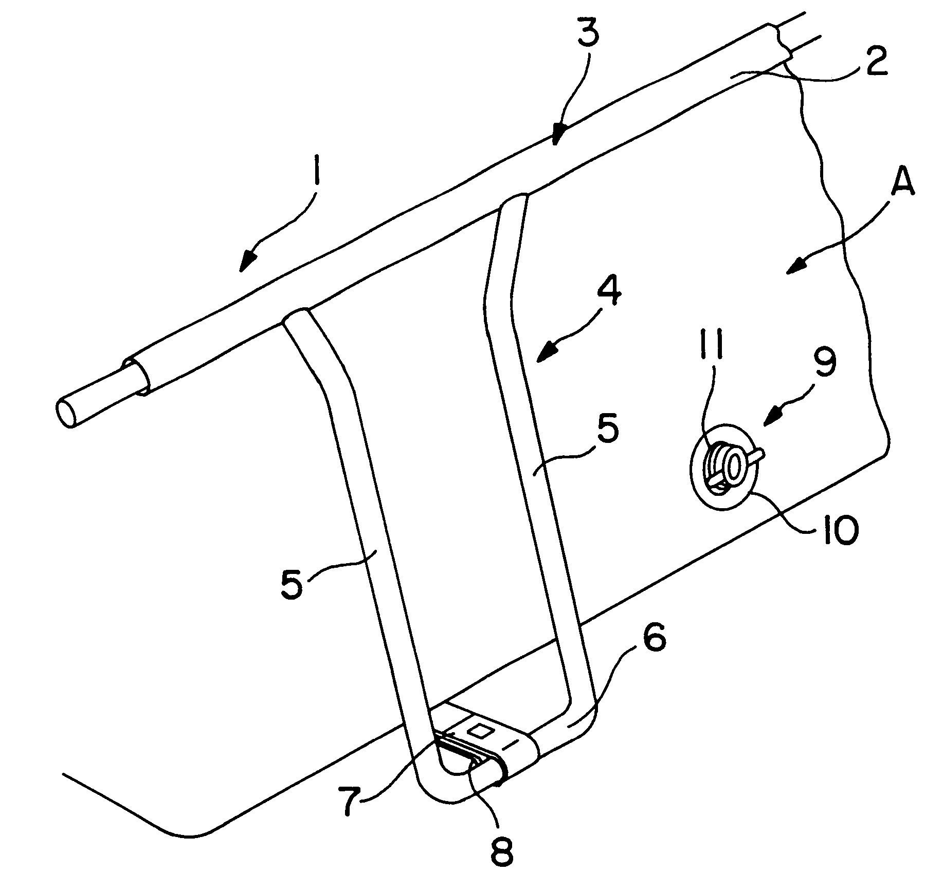
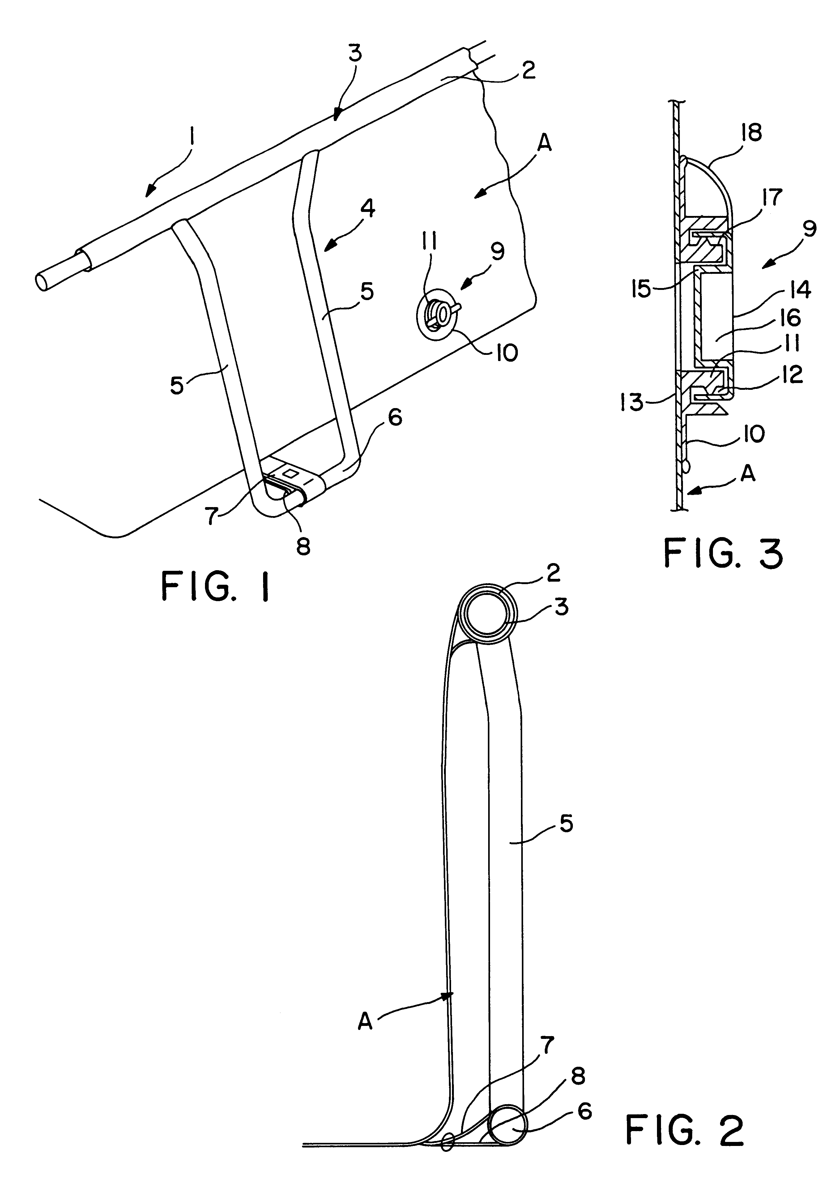
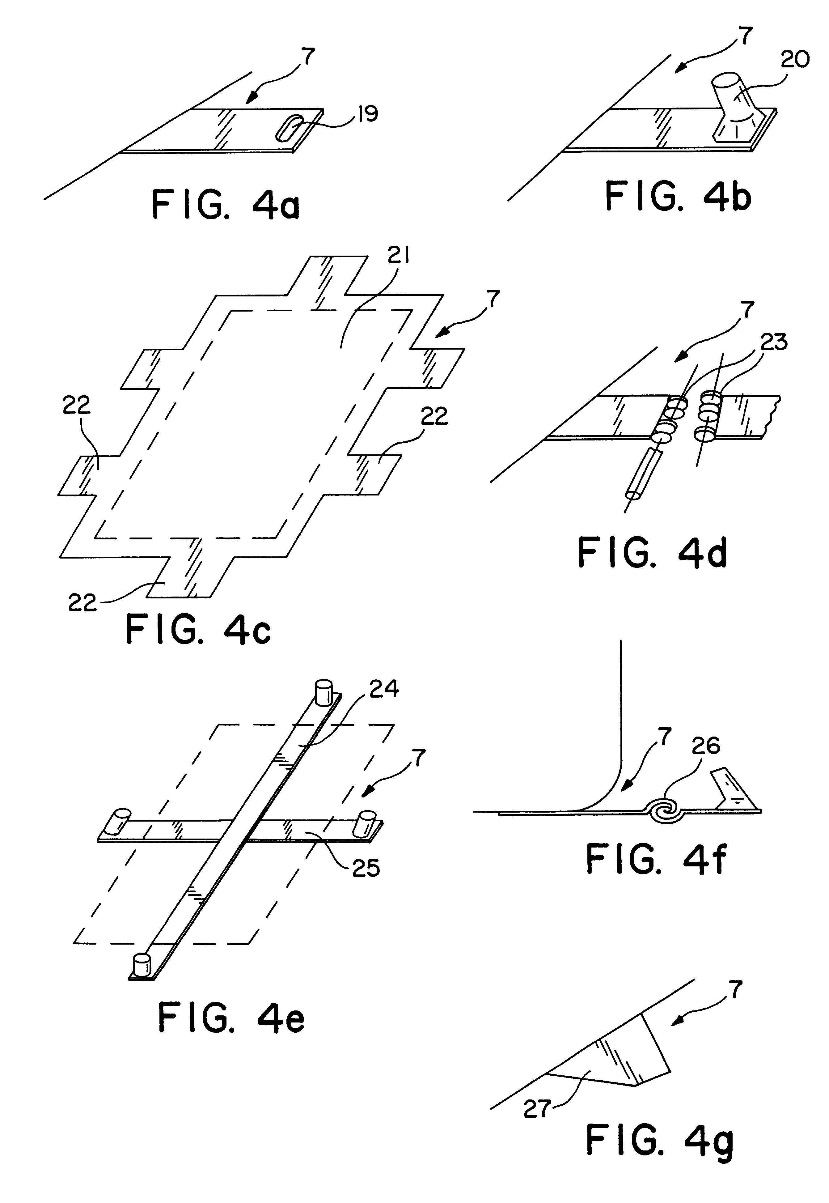
As illustrated in the drawings, and in particular with reference to FIG. 1, the improvement in swimming pools or other impoundments according to the present invention has been incorporated in a support structure 1 comprised of upper beams 3 which are in turn comprised of the upper frame element 2 of the structure 1, wherewith a plurality of leg members 4 spaced equidistantly extend from said frame element 2, each of which leg members 4 comprises laterally disposed tubular leg elements 5 and a foot member 6 (lower crossbar of the leg member 4) to which foot member 6 a strip 7 with end loop 8 is attached, wherewith the strips 7 are supported by the bottom membrane component of the swimming pool A, and wherewith on one of the lateral membrane walls of the swimming pool A an outlet device 9 is provided which is fixed to said membrane by heat welding or similar means and which is comprised of a laminar portion in the form of an annular piece 10 which surrounds a tubular (nipple-like) por...


PUM


Abstract

The present invention relates to improvements in swimming pools or other impoundments (hereinafter, "swimming pools"), for use in patios, gardens, open spaces, and around homes, which have an upper frame that supports a membrane which contains the contents of the pool, which upper frame is connected to support legs. The bottom of the pool has extensions or strips which are bent into a loop to engage a crossbar or other engaging member at the foot of each said leg and one of the lateral walls of the pool contains an annular laminar insert which extends radially from a tubular projecting member which has a double wall which defines a space in which a lateral wall of a plug is compressively engaged, which plug is connected via a laminar strip to the annular laminar insert, wherewith said plug also has a double wall which defines an annular recess, and wherewith the internal surface of the said cylindrical space or said cylindrical recess bears a ridge which extends around the entire circumferential extent of said surface. The strips may have a variety of configurations.

Description

1. Field of the InventionThe present invention relates to an improvement in swimming pools or other impoundments (hereinafter, "swimming pools"), for use in patios, gardens, open spaces, around homes. More specifically, the present invention relates to swimming pools comprised of canvas or similar material (hereinafter, "membrane"), which are easily assembled or disassembled, and in particular comprise a tubular structure which can be disassembled. This tubular structure serves as support and is connected to the edge regions (or edge loops) of the membrane. The membrane defines the space for containing the water.2. Description of the Related ArtSwimming pools comprised of membranes of various materials (e.g. canvas or plastic), can be erected rapidly in a patio or garden, and have come into widespread use because they allow one to make effective use of a space without suffering major modification of that space.These swimming pools are generally comprised of a tubular structure which...

Claims


Application Information

Patent Timeline
Patent Type & Authority Patents(United States)
IPC IPC(8): E04H4/00
CPCE04H4/0056
Inventor MUSSA, EDUARDO ALBERTO
Owner MUSSA EDUARDO ALBERTO
Why Eureka
Try Eureka