Electric wire connector for press connecting electric wires
a technology of electric wire and connector, which is applied in the direction of fastening/insulating connecting parts, contact members penetrating/cutting insulation/cable strands, electrical apparatus, etc., can solve the problems of complicated and troublesome connection operation, and the safety of electric shock is not guaranteed, so as to achieve rapid and easy connection of a plurality of connections
- Summary
- Abstract
- Description
- Claims
- Application Information
AI Technical Summary
Benefits of technology
Problems solved by technology
Method used
Image
Examples
first embodiment
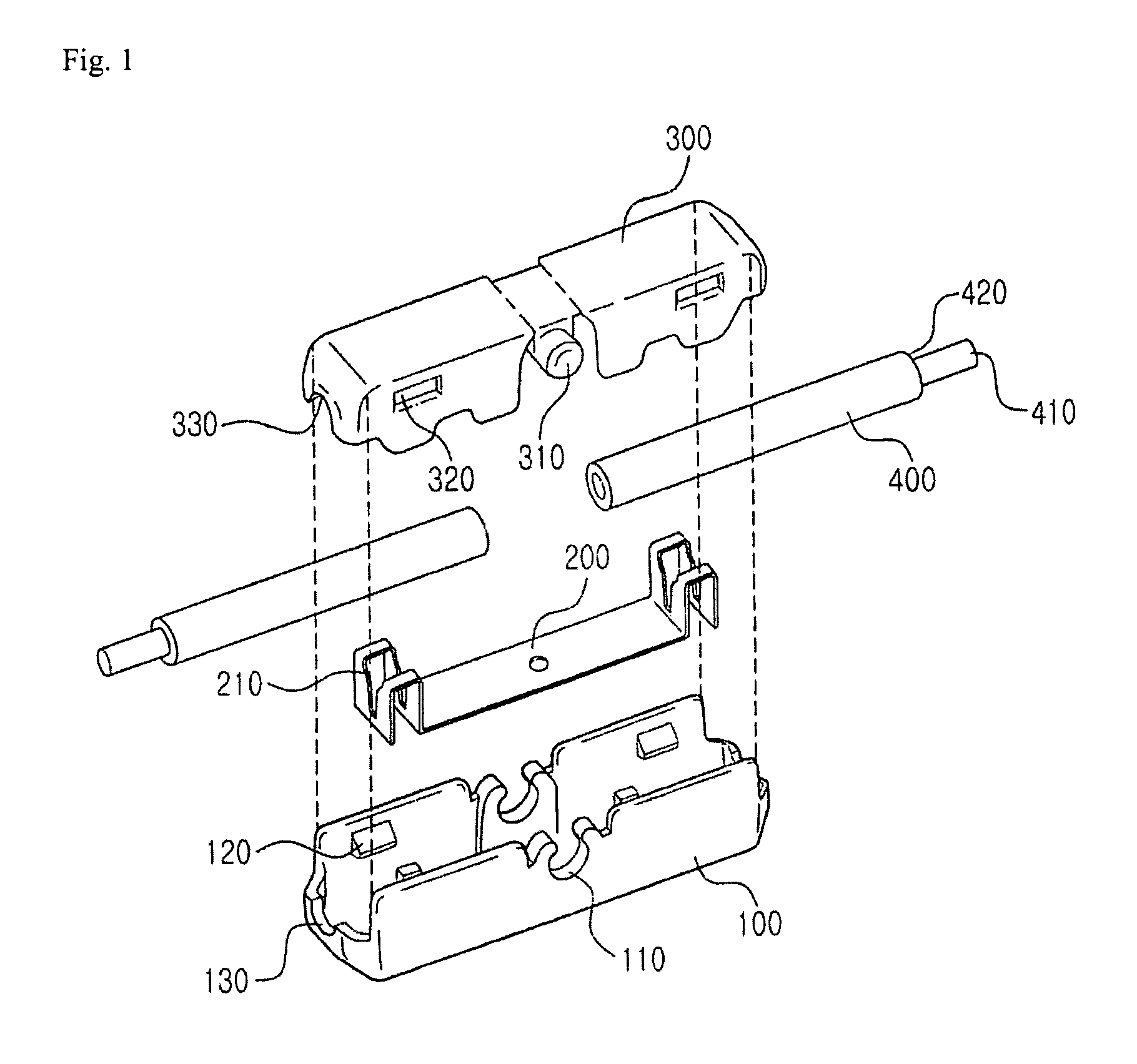
[0030]Hereinafter, an electric wire connector according to the present invention will be described in detail with reference to FIGS. 1 to 4.
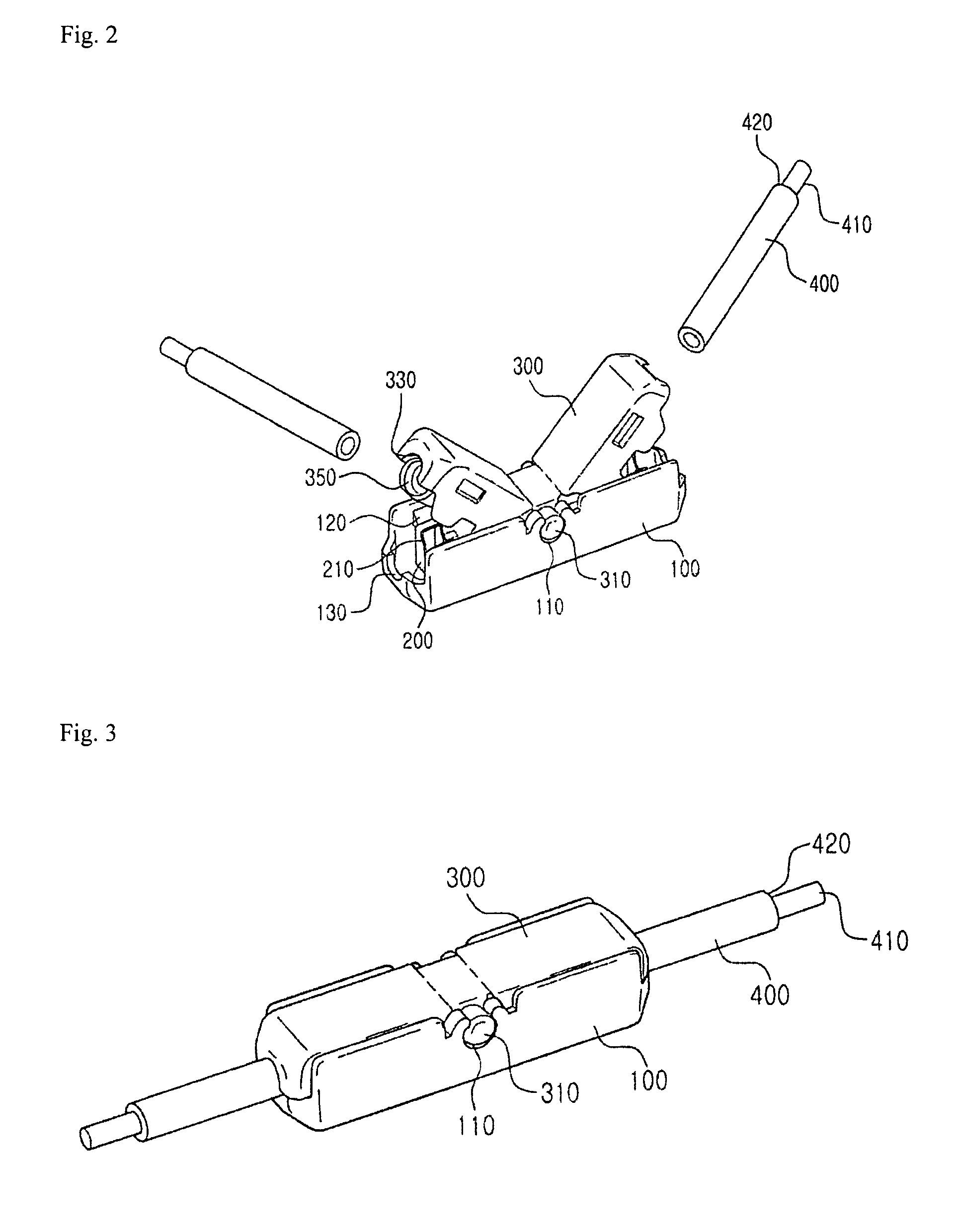
[0031]FIG. 1 is an exploded view illustrating an electric wire connector according to a first embodiment of the present invention, FIG. 2 is a construction view of the electric wire connector shown in FIG. 1 before electric wires are inserted into the electric wire connector, FIG. 3 is a construction view of the electric wire connector shown in FIG. 1 after electric wires are inserted into the electric wire connector, and FIG. 4 is a sectional view of the electric wire connector shown in FIG. 3.
[0032]Referring to FIGS. 1 to 4, the electric wire connector according to the first embodiment of the present invention includes a lower connector 100, an upper connector 300, and a conductive member 200.
[0033]The lower connector 100 is a receiving body which is open at the top thereof. The lower connector 100 is formed in a shape extending in the longitu...
second embodiment
[0063]Hereinafter, an electric wire connector according to the present invention will be described in detail with reference to FIGS. 5 and 6.
[0064]FIG. 5 is an exploded view illustrating an electric wire connector according to a second embodiment of the present invention, and FIG. 6 is a coupled view of the electric wire connector shown in FIG. 5.
[0065]Referring to FIGS. 5 and 6, the electric wire connector according to the second embodiment of the present invention is used to connect two electric wires 650 to each other in a “T” shape. Specifically, the electric wire connector electrically connects a first electric wire 650 extending in one direction and a second electric wire 650 extending in the direction perpendicular to the first electric wire 650 to each other.
[0066]In the same manner as the first embodiment, the “T” type electric wire connector includes a lower connector 500, a conductive member 550, and an upper connector 600. The structure of one side of the “T” type electr...
third embodiment
[0072]Hereinafter, an electric wire connector according to the present invention will be described in detail with reference to FIGS. 7 to 9.
[0073]FIG. 7 is an exploded view illustrating an electric wire connector according to a third embodiment of the present invention. FIGS. 8 and 9 are coupled views of the electric wire connector shown in FIG. 7.
[0074]Referring to FIG. 7, the electric wire connector according to the third embodiment of the present invention includes a lower connector 700, a conductive member 750, an upper connector 800, and two fixing pieces 850.
[0075]The lower connector 700 is a receiving body which is open at the top thereof. The lower connector 700 is formed in a shape extending in the longitudinal direction thereof. The lower connector 700 has a space for receiving the conductive member 700 and electric wires 950 therein.
[0076]The lower connector 700 is provided at the front and rear thereof with insertion holes 720 through which the electric wires 950 are ins...
PUM
 Abstract
Description
Claims
Application Information
 - R&D
- Intellectual Property
- Life Sciences
- Materials
- Tech Scout
- Unparalleled Data Quality
- Higher Quality Content
- 60% Fewer Hallucinations
Browse by: Latest US Patents, China's latest patents, Technical Efficacy Thesaurus, Application Domain, Technology Topic, Popular Technical Reports.
© 2025 PatSnap. All rights reserved.Legal|Privacy policy|Modern Slavery Act Transparency Statement|Sitemap|About US| Contact US: help@patsnap.com


