Electric wire connector

Active Publication Date: 2011-03-17
JOWOO TECH
View PDF11 Cites 4 Cited by
  • Summary
  • Abstract
  • Description
  • Claims
  • Application Information

AI Technical Summary

Benefits of technology

[0006]Therefore, the present invention has been made in view of the above problems, and it is an object of the present invention to provide an electric wire connector that is capable of rapidly and easily connecting a plurality of electric wires to each other without using a special tool and without peeling off sheaths of the respective electric wires.

Problems solved by technology

Furthermore, the connection operation is complicated and troublesome.
In addition, safety against electric shock is not guaranteed.

Method used


Image

  • Electric wire connector
  • Electric wire connector
  • Electric wire connector

Examples


first embodiment

[0030]Hereinafter, an electric wire connector according to the present invention will be described in detail with reference to FIGS. 1 to 4.

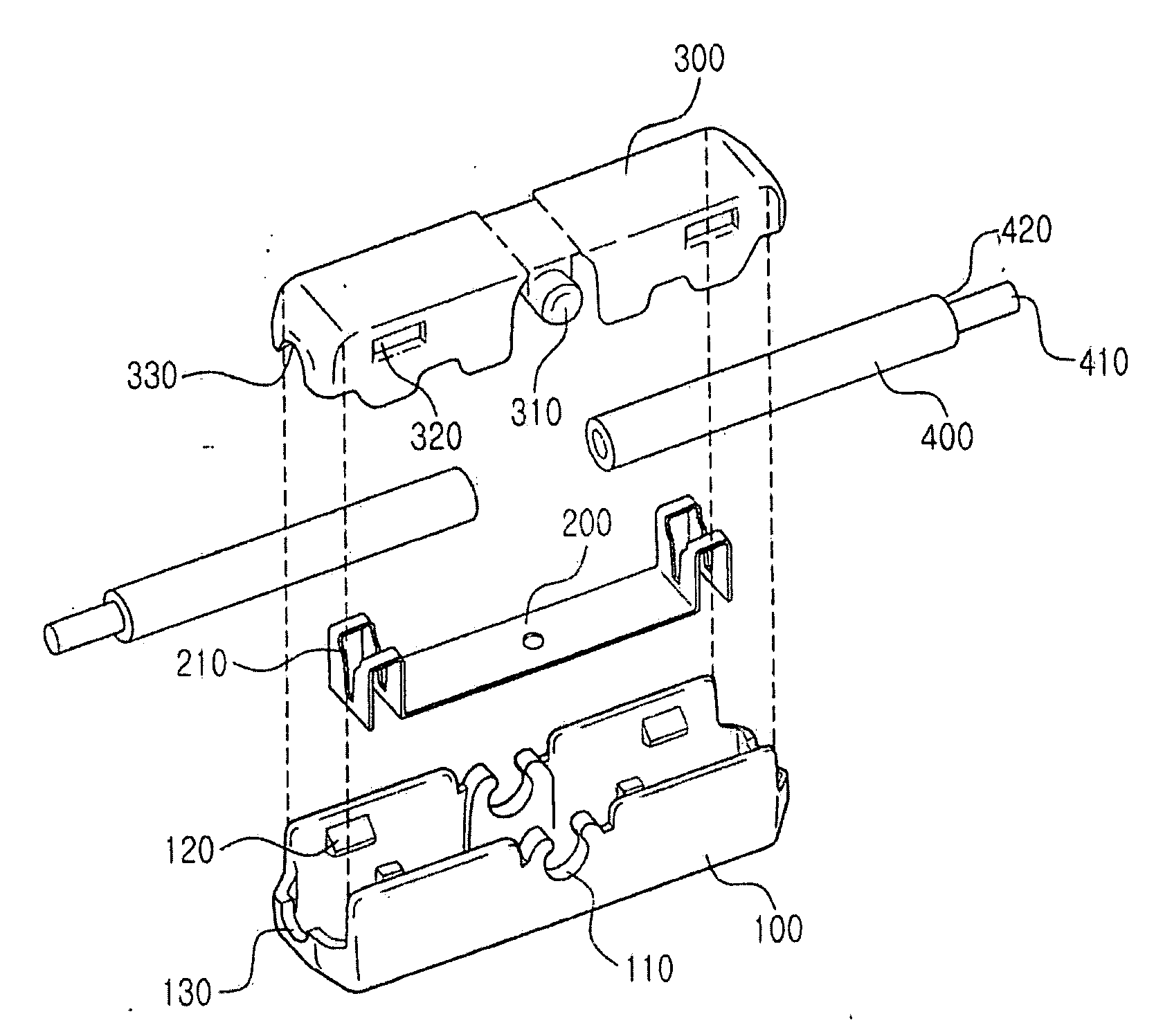
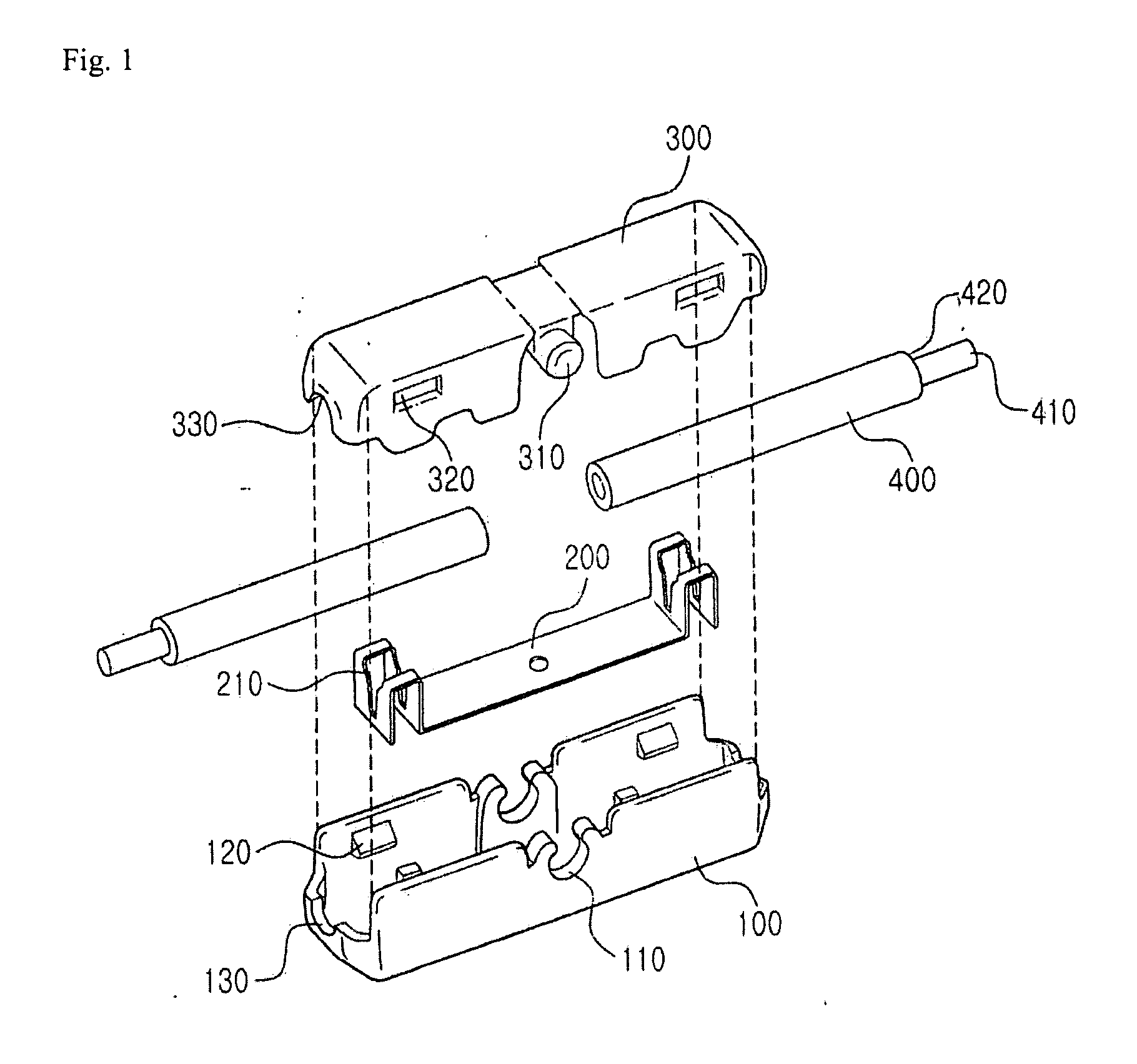
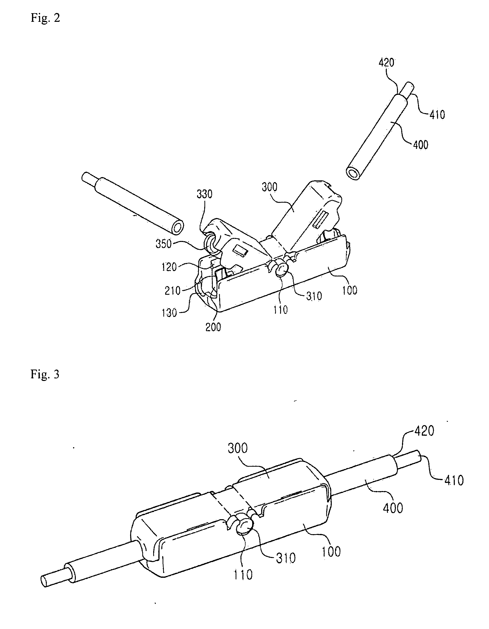
[0031]FIG. 1 is an exploded view illustrating an electric wire connector according to a first embodiment of the present invention, FIG. 2 is a construction view of the electric wire connector shown in FIG. 1 before electric wires are inserted into the electric wire connector, FIG. 3 is a construction view of the electric wire connector shown in FIG. 1 after electric wires are inserted into the electric wire connector, and FIG. 4 is a sectional view of the electric wire connector shown in FIG. 3.

[0032]Referring to FIGS. 1 to 4, the electric wire connector according to the first embodiment of the present invention includes a lower connector 100, an upper connector 300, and a conductive member 200.

[0033]The lower connector 100 is a receiving body which is open at the top thereof. The lower connector 100 is formed in a shape extending in the longitu...

second embodiment

[0063]Hereinafter, an electric wire connector according to the present invention will be described in detail with reference to FIGS. 5 and 6.

[0064]FIG. 5 is an exploded view illustrating an electric wire connector according to a second embodiment of the present invention, and FIG. 6 is a coupled view of the electric wire connector shown in FIG. 5.

[0065]Referring to FIGS. 5 and 6, the electric wire connector according to the second embodiment of the present invention is used to connect two electric wires 650 to each other in a “T” shape. Specifically, the electric wire connector electrically connects a first electric wire 650 extending in one direction and a second electric wire 650 extending in the direction perpendicular to the first electric wire 650 to each other.

[0066]In the same manner as the first embodiment, the “T” type electric wire connector includes a lower connector 500, a conductive member 550, and an upper connector 600. The structure of one side of the “T” type electr...

third embodiment

[0072]Hereinafter, an electric wire connector according to the present invention will be described in detail with reference to FIGS. 7 to 9.

[0073]FIG. 7 is an exploded view illustrating an electric wire connector according to a third embodiment of the present invention. FIGS. 8 and 9 are coupled views of the electric wire connector shown in FIG. 7.

[0074]Referring to FIG. 7, the electric wire connector according to the third embodiment of the present invention includes a lower connector 700, a conductive member 750, an upper connector 800, and two fixing pieces 850. The lower connector 700 is a receiving body which is open at the top thereof.

[0075]The lower connector 700 is formed in a shape extending in the longitudinal direction thereof. The lower connector 700 has a space for receiving the conductive member 700 and electric wires 950 therein.

[0076]The lower connector 700 is provided at the front and rear thereof with insertion holes 720 through which the electric wires 950 are ins...


PUM


Abstract

An electric wire connector is disclosed. The electric wire connector includes an insulative lower connector formed in a shape extending in a first direction, the lower connector being open at a top thereof, the lower connector being provided at sides thereof with a plurality of fixing protrusions and shaft openings, an insulative upper connector formed in a shape extending in the first direction, the upper connector being open at a bottom thereof, the upper connector being provided at sides thereof with fixing holes into which the fixing protrusions of the lower connector are inserted and a fixing shaft inserted through the shaft openings of the lower connector, and a conductive member disposed in the lower connector, the conductive member having a plurality of cutting blades for peeling off sheaths of electric wires, the cutting blades being electrically connected to cores of the electric wires.

Description

BACKGROUND OF THE INVENTION[0001]1. Field of the Invention[0002]The present invention relates to an electric wire connector, and, more particularly, to an electric wire connector that is capable of connecting electric wires to each other without peeling off sheaths of the respective electric wires.[0003]2. Description of the Related Art[0004]Connection between two or more separate electric wires may be achieved using a method of peeling sheaths of the electric wires, connecting exposed cores of the electric wires, and wrapping the connected cores with an insulating tape.[0005]In the method using insulating tape, however, a tool for twisting the cores of the electric wires is needed. Furthermore, the connection operation is complicated and troublesome. In addition, safety against electric shock is not guaranteed.SUMMARY OF THE INVENTION[0006]Therefore, the present invention has been made in view of the above problems, and it is an object of the present invention to provide an electri...

Claims


Application Information

Patent Timeline
IPC IPC(8): H01R4/24
CPCH01R4/2433H01R9/11H01R11/11
Inventor LEE, YOUNGHWAN
Owner JOWOO TECH
Why Eureka
Try Eureka