
Solar energy collection

a technology of solar energy and solar collectors, applied in solar heat storage, solar heat systems, lighting and heating apparatuses, etc., can solve the problems of vapor phase pumping arrangement, disadvantage of not filling tubular absorbers, and many limitations, and the majority of this thermal energy will be lost to the ambien

Active Publication Date: 2011-12-15
AIL RES
View PDF1 Cites 12 Cited by
  • Summary
  • Abstract
  • Description
  • Claims
  • Application Information

AI Technical Summary

Problems solved by technology

It has generally been viewed as disadvantageous not to fill the tubular absorbers such that the top half is in contact with the liquid.
The vapor-phase-pumping arrangement described above, however, has several limitations.
Most of this thermal energy will be lost to the ambient during the night.
Furthermore, if the fluid within the tubular absorber is water, the absorber is likely to be damaged by freezing in cold climates since water expands when it freezes.
This tube, which is often metallic as to withstand possible stagnation conditions within the evacuated-tube collector, increases the cost for the solar collector, especially for more expensive metals such as copper.

Method used


Image

  • Solar energy collection
  • Solar energy collection
  • Solar energy collection

Examples


Embodiment Construction

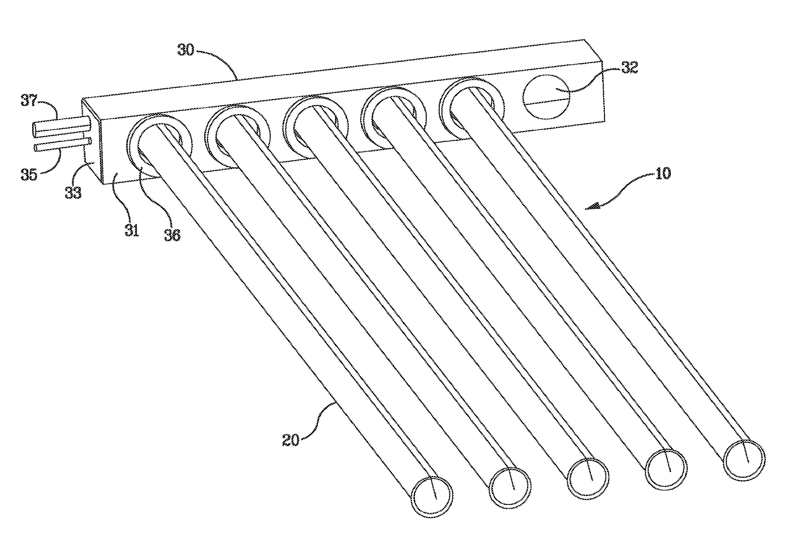
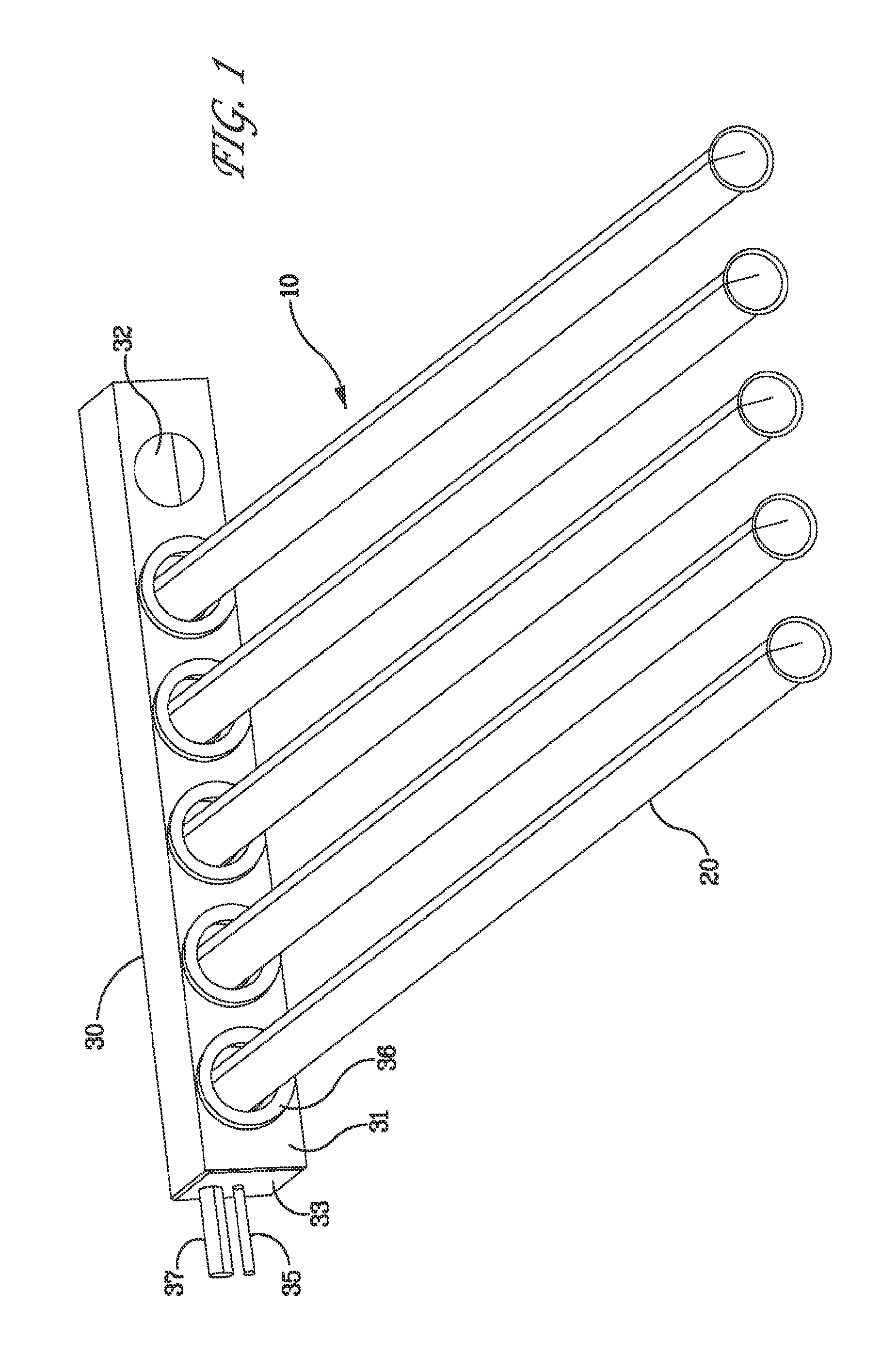
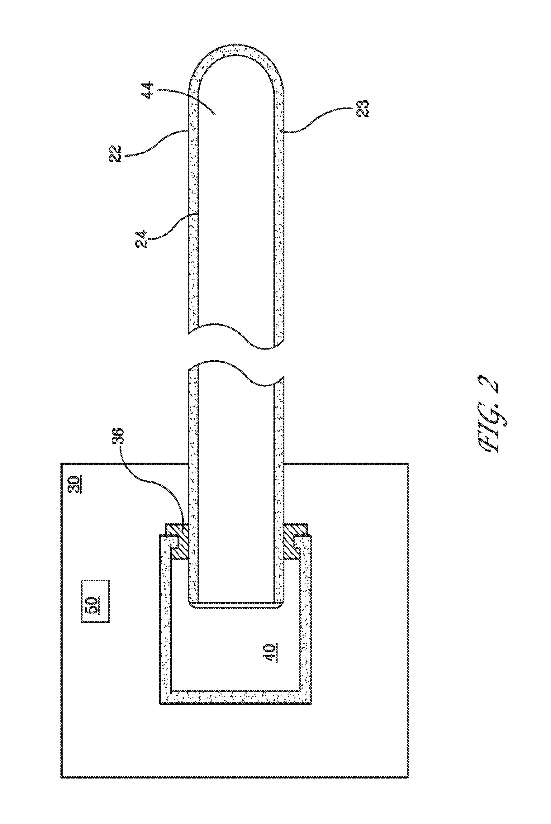
[0022]A solar collector apparatus with Dewar-type evacuated tubes is generally described. The tubes may be oriented essentially horizontally and partially filled with liquid unlike a prior art solar collection apparatus that operates with liquid filling the tube almost to the top. Instead, the tubes of embodiments of the present invention may be filled only partially with liquid so that the space for vapor above the liquid extends more than three-quarters the length of the tube. With the tubes oriented close to horizontal and partially filled with liquid, the vapor produced within the tube can leave the tube without interfering with the entering liquid. Such a configuration, specifically the relatively low amount of liquid within the tube, reduces the heat lost during the night and, in applications where the tubes are less than half filled with liquid, a liquid that expands during freezing can do so within the tube without creating high stresses that might damage the tube.

[0023]An e...


PUM


Abstract

A solar collector apparatus with Dewar-type evacuated tubes results in the more efficient collection of solar radiation by, for example, maintaining the level of a volatile liquid flowing into the solar collector so that no more than 80% of the volume of an inner cylinder of a collection tube is filled with liquid and a corresponding manifold collects the vapor produced when heat is transferred from the surface of the inner glass cylinder that absorbs solar radiation to the volatile liquid. The aforementioned apparatus may likewise be used to heat a liquid within an absorber tube, the liquid having a volatile and a non-volatile component. As heat is transferred to the liquid, a fraction of the volatile component is converted to vapor, leaving the liquid more concentrated in the non-volatile component.

Description

BACKGROUND OF THE INVENTION[0001]1. Field of the Invention[0002]The present invention generally concerns solar energy collection. More specifically, the present invention concerns increasing the efficiency of a tubular solar collector apparatus.[0003]2. Description of the Related Art[0004]The application of solar energy to heating generally requires a collector that efficiently absorbs solar radiation. The collector transfers the radiated energy to a fluid, which transports the energy to a final application in the form of heat. This final application may include a domestic water or space heating apparatus. An effective collector must absorb a high percentage of incident solar radiation, while losing only a small amount of the absorbed energy to the ambient through either heat conduction or radiation.[0005]Solar collectors including two concentric glass tubes with an evacuated space there between have generally been recognized as an effective configuration for absorbing a high percen...

Claims


Application Information

Patent Timeline
Patent Type & Authority Applications(United States)
IPC IPC(8): F24J2/32F24J2/24F24J2/48F24J2/05F24S10/40F24S10/70F24S10/95
CPCF24J2/055F24J2/32F24J2/4647Y02E10/44F24J2/345F24S10/45F24S10/95F24S60/30F24S80/30
Inventor LOWENSTEIN, ANDREW
Owner AIL RES
Learn More