Binary Hydraulic Manifold System

Active Publication Date: 2011-12-15
SALFORD BBI
View PDF4 Cites 3 Cited by
  • Summary
  • Abstract
  • Description
  • Claims
  • Application Information

AI Technical Summary

Benefits of technology

[0005]The binary hydraulic manifold system of the present disclosure is designed to meet and overcome the aforementioned disadvantages of a typical or conventional spreader system. More particularly, the present binary hydraulic manifold system meets these needs. For example, all of the valves can be easily changed without loosening or removing any hydraulic hoses, thus preventing oil loss, reducing labor costs, and providing quick diagnosis of any performance issues. For example, if a valve fails during operation, it can be replaced easily and quickly by rem

Problems solved by technology

They present a complicated maze of hydraulic lines and associated valves and other equipment for operating the hydraulic systems.
Maintenance of such systems is difficult and time consuming.
Should, for ex

Method used


Image

  • Binary Hydraulic Manifold System
  • Binary Hydraulic Manifold System
  • Binary Hydraulic Manifold System

Examples


Example

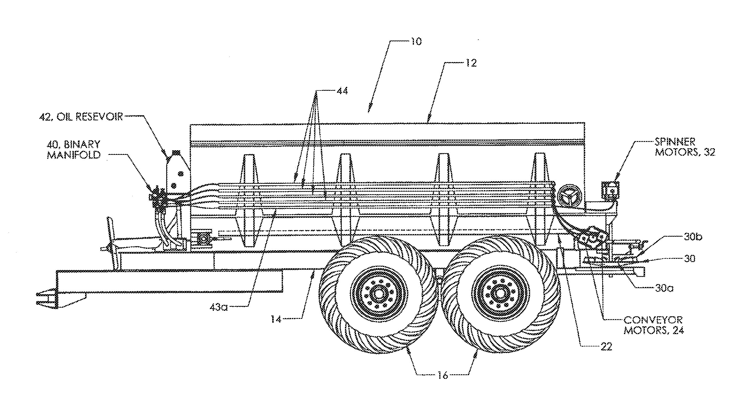
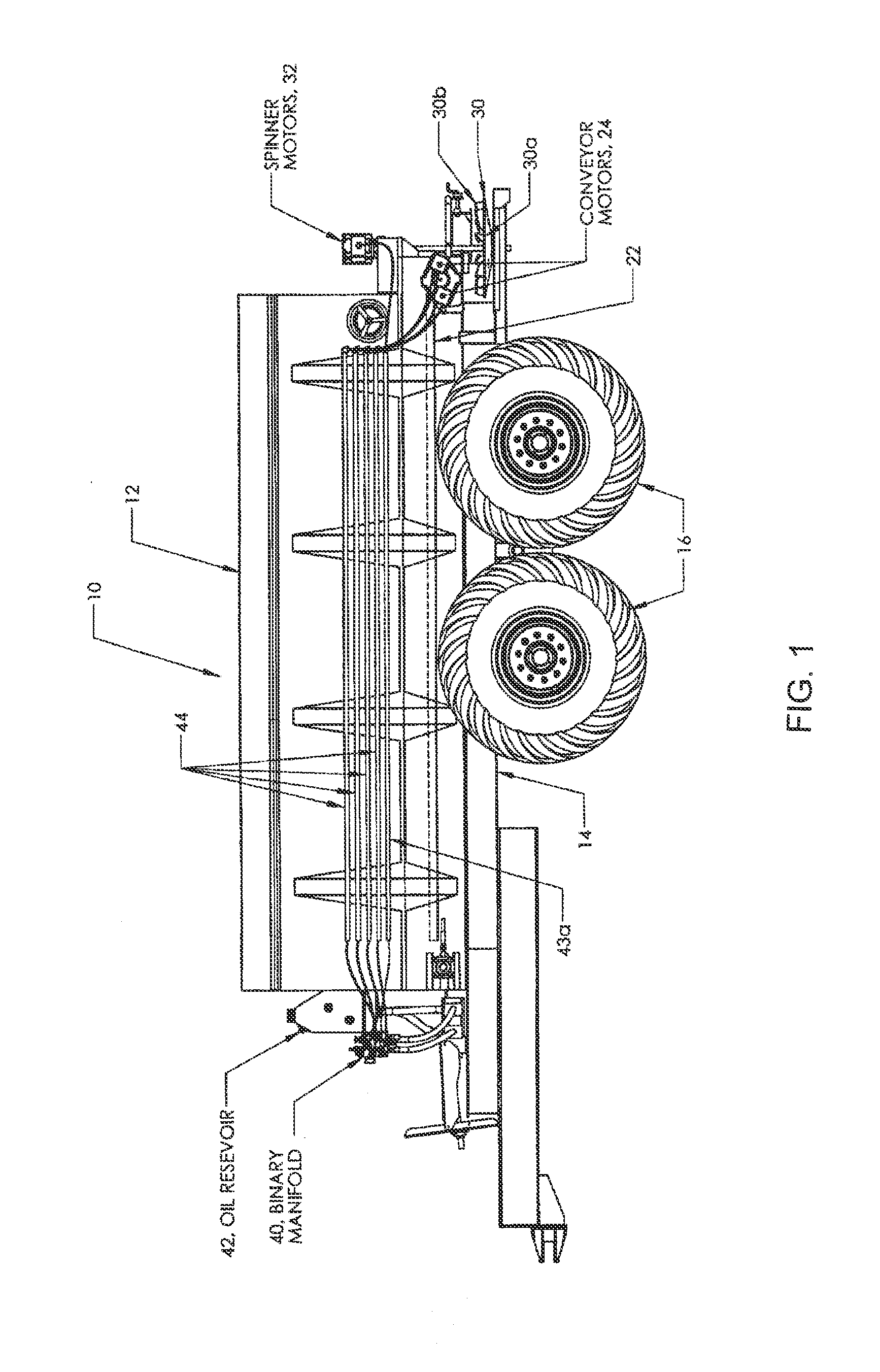
[0020]Referring more specifically to the drawings in which like reference numerals refer to like elements throughout the several views, an exemplary non-limiting embodiment of the binary hydraulic manifold system of the present disclosure is illustrated in FIGS. 1-4. Referring to FIG. 1, one embodiment of a spreader 10 of the present disclosure is illustrated. The spreader 10 includes one or more bins or hoppers 12 mounted on a mobile frame 14 carried by wheels 16. In one embodiment the wheeled frame is designed to be pulled by a tractor (not shown). Each bin or hopper has generally converging walls leading to a discharge port (not shown), allowing for gravitational feed and discharge of material ingredients contained within each respective bin or hopper to the conveyor(s). The bins or hoppers are generally designed for holding and discharging dry, bulk granular materials such as but not limited to fertilizer, fertilizer supplements, herbicides, insecticides, fungicides, soil pH adj...


PUM


Abstract

A hydraulic fluid manifold system for a spreader, the spreader including at least one bin for holding dry bulk material for distribution to at least one conveyor associated with the bin for receiving the dry bulk material from the at least one bin and transporting the dry bulk material to at least one spinner associated with the spreader. The hydraulic fluid manifold system includes a single, unitary manifold including a variable speed fluid control circuit for setting a speed for the at least one conveyor and a variable speed fluid control circuit for the at least one spinner of a spreader system for setting a speed for the at least one spinner, the variable speed control circuit for the at least one conveyor including an on/off device for the at least one conveyor that allows when fluid flow through the variable speed conveyor circuit to the at least one conveyor is turned on that the at least one conveyor can automatically operate at a speed set for the at least one conveyor prior to fluid flow to the at least one conveyor having been turned off. Further, the spreader can include at least two conveyors, and the variable speed control circuit for the at least two conveyors can further include flow of hydraulic fluid through the variable speed conveyor circuit to be changed between in-parallel flow to a first and a second of the conveyors simultaneously and in-series flow where flow of fluid is sent to a first one of the conveyors and then sent from the first one of the conveyors to a second one of the two conveyors.

Description

CROSS-REFERENCE TO RELATED APPLICATION[0001]This application claims priority to and the benefit of co-pending U.S. provisional application entitled, “Binary Hydraulic Manifold System,” having Ser. No. 61 / 354,804, filed Jun. 15, 2010, which is entirely incorporated herein by reference.FIELD OF THE DISCLOSURE[0002]The present disclosure relates to a spreader system of the type used to distribute one or more material ingredients, such as dry bulk material, for example fertilizer and fertilizer supplements, compost, poultry litter, gravel, sand and other granular materials, and broadcast them over a ground surface such as an agricultural field, road or other surfaces.BACKGROUND OF THE DISCLOSURE[0003]It is generally known to provide a spreader system for spreading or broadcasting ingredients, such as fertilizer and fertilizer supplements, organics, sand and other granular materials over a ground surface. A conventional spreader has one or more bins or hoppers for holding dry bulk materi...

Claims


Application Information

Patent Timeline
IPC IPC(8): F17D3/00
CPCF17D3/00A01C19/00Y10T137/86493
Inventor OWENBY, STEVECHIPMAN, MICHAELBATTLE, TED
Owner SALFORD BBI
Why Eureka
Try Eureka