Gimbal positioning with target velocity compensation

a technology of target velocity and compensation, which is applied in the direction of instruments, instruments for comonautical navigation, optical radiation measurement, etc., can solve the problem of complicated maintenance of the gimbal pointing toward the target obj

Active Publication Date: 2011-12-15
TELEDYNE FLIR LLC
View PDF6 Cites 44 Cited by
  • Summary
  • Abstract
  • Description
  • Claims
  • Application Information

AI Technical Summary

Problems solved by technology

However, keeping the gimbal pointing toward a target object

Method used


Image

  • Gimbal positioning with target velocity compensation
  • Gimbal positioning with target velocity compensation
  • Gimbal positioning with target velocity compensation

Examples


example 1

B. Example 1

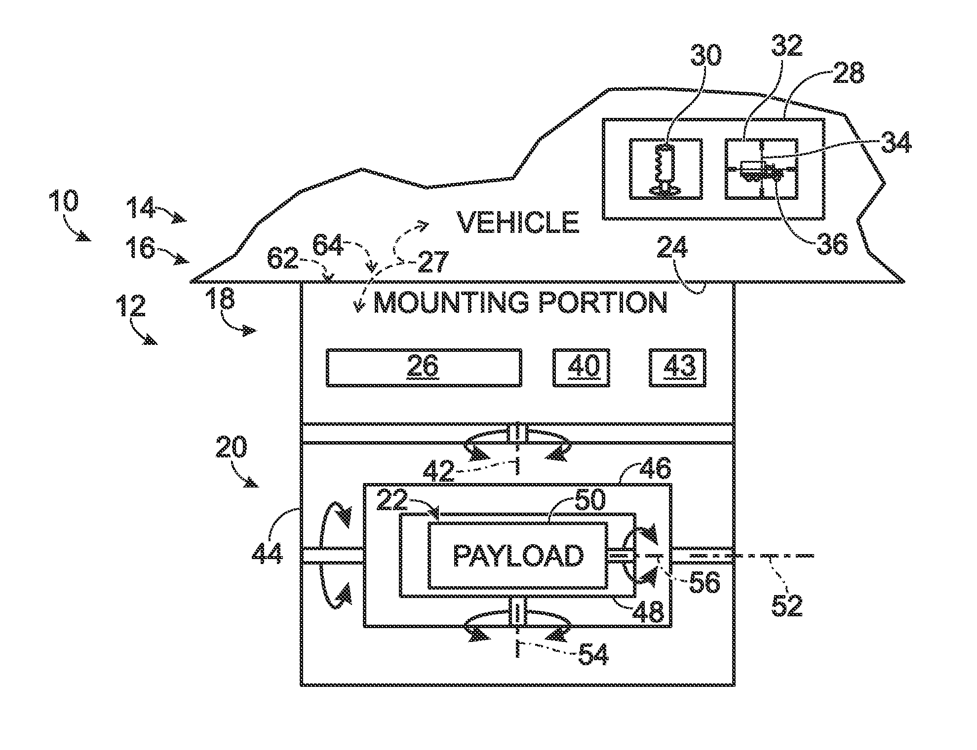
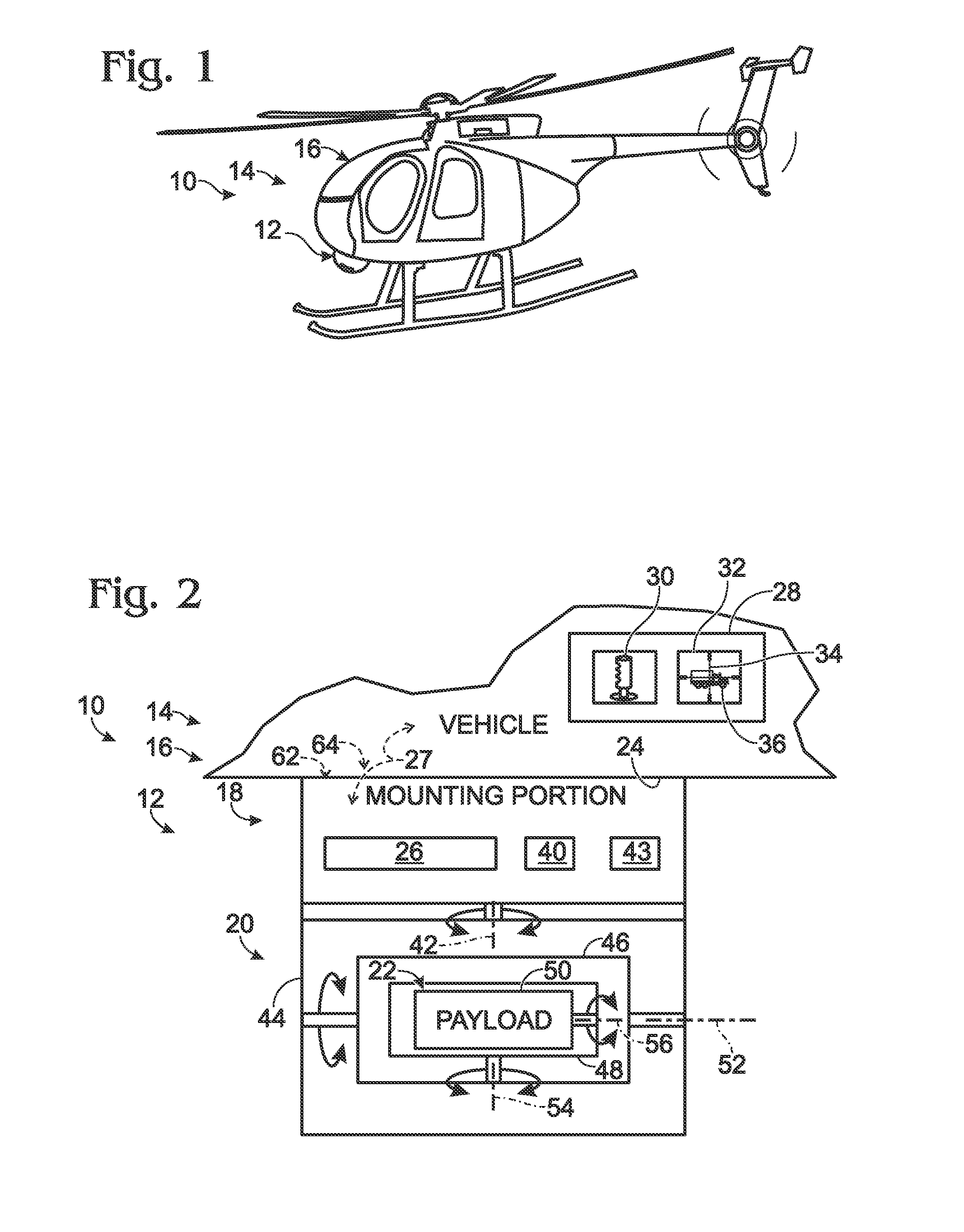
[0048]As described above, transforming platform and target positions into gimbal rotation commands that result in pointing a sensor at a target generally may be accomplished through the application of various vector rotations and coordinate transformations. For example, using the previously introduced notation, an exemplary transformation procedure would include the following steps, where it is assumed that the gimbal and target positions are known in the ECEF coordinate system.

[0049]Starting with the gimbal and target position vectors in the ECEF frame, the gimbal to target displacement vector may be determined in the ECEF frame by vector subtraction:

e{right arrow over (X)}ot=e{right arrow over (X)}et−e{right arrow over (X)}eo

The target displacement vector then may be determined in the navigation frame and the optical frame through successive application of the appropriate transformation matrices:

n{right arrow over (X)}ot=Cen×e{right arrow over (X)}ot

o{right arrow ove...

example 2

D. Example 2

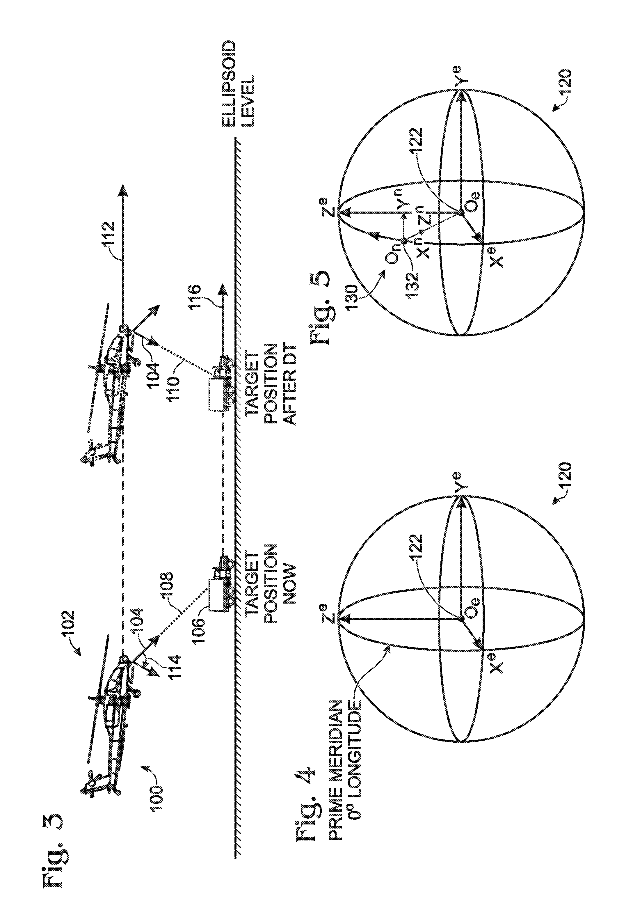
[0052]The rates of change of the gimbal azimuth and elevation angles to keep the gimbal line of sight pointed toward the target may be determined from (i) an initially determined target displacement vector in the navigation frame, (ii) initially determined azimuth and elevation angles to point the gimbal toward the target, and (iii) the known or estimated velocities of the gimbal platform and the target, as described below.

[0053]A new target displacement vector may be determined from the previous target displacement vector by subtracting the change in position of the platform and adding the change in position of the target:

n{right arrow over (X)}oT(t+Δt)=n{right arrow over (X)}oT(t)−n{right arrow over (X)}oF+n{right arrow over (V)}TΔt

The new target displacement vector then may be rotated into the optical frame:

o{right arrow over (X)}oT(t+Δt)=Cbn×n{right arrow over (X)}oT(t+Δt)

and then into the gimbal azimuth yoke frame:

gmb{right arrow over (X)}oT(t+Δt)=Cbgmb×o{right ar...


PUM


Abstract

A gimbal system, including components and methods of use, configured to track moving targets. More specifically, the disclosed system may be configured to orient and maintain the line of sight (“los”) of the gimbal system toward a target, as the target and, in some cases, the platform supporting the gimbal system are moving. The system also may be configured to calculate an estimated target velocity based on user input, and to compute subsequent target positions from previous positions by integrating the estimated target velocity over time. A variety of filters and other mechanisms may be used to enable a user to input information regarding a target velocity into a gimbal controller.

Description

INTRODUCTION[0001]Imaging systems, light sources, weapons, and other devices can be mounted and used on a variety of supports. For example, moving vehicles, including various aircraft, watercraft, and ground vehicles, can provide versatile supports capable of transporting such devices. Many devices benefit from being easily and accurately pointed at a desired target. Gimbal systems can be used, alone or with gyroscopic stabilization, easily and accurately to point such devices without necessarily having to reorient the supports to which the devices are mounted.[0002]Gimbal systems, as used herein, are any device-mounting mechanisms that include at least two different, typically mutually perpendicular, axes of rotation, thus providing angular movement in at least two directions (e.g., pan and tilt, among others). A gimbal system can include one or more constituent gimbals, each of which can rotate relative to one or more other constituent gimbals and / or a supported payload. A gimbal ...

Claims


Application Information

Patent Timeline
IPC IPC(8): H04N5/225G01J1/20
CPCH04N5/33G01C21/18
Inventor EVANS, STEWART W.WILLIAMS, ANCA G.
Owner TELEDYNE FLIR LLC
Why Eureka
Try Eureka