
Swim Fin Boot

a technology for swimming fins and booties, applied in the field of footwear, can solve the problems of cumbersome operation, flimsy wrap-around ankle straps, and easy breakage or slippage of ankle straps,

Inactive Publication Date: 2011-12-22
MONTEMURRO DAVID
View PDF15 Cites 10 Cited by
  • Summary
  • Abstract
  • Description
  • Claims
  • Application Information

AI Technical Summary

Benefits of technology

[0011]Another object of this invention is to provide a swim fin boot, as aforesaid, that securely connects a swim fin portion with an ankle portion for a comfortable fit.
[0015]A still further object of this invention is to provide a swim fin boot, as aforesaid, that includes a predetermined ratio of fin stiffness and flexibility.

Problems solved by technology

Each of these approaches, however, has disadvantages and shortcomings.
Specifically, the wrap-around ankle strap is flimsy and can easily break apart or slip out of place.
Fastening straps that clamp over the dorsal instep are cumbersome to operate and are typically made of plastic or metal, both of which are undesirable materials for water-sport devices in that the plastic dries out and the metal may rust.
While such straps are making a well known appearance into the worlds of athletic and sports footwear generally (e.g., cycling shoes, ski boots, motorcycle boots, and even some sprinters' spikes etc.), they have proven undesirable for middle to upper market swim fins.
And further, while the sports sandal may have a certain aesthetic appeal to sports-minded individuals—reminiscent of cross training shoes, hiking sandals and even so called “flip-flop” shoes in some cases—they are not appropriate for all swim-fin applications.
These too leave some divers, surfers, and body boarders underserved by their swim fins.
Extensible fins provide a convenient means by which to manually adjust the force versus flexibility ratio of a given fin, but the manual adjustment is often inconvenient, and inadvertent adjustments or slippage can occur with the extensible portion.
Conversely, anterior side ribs are well known in the art, but place substantially all of the rigidity on the side to the fins while typically leaving the center regions flimsy and susceptible to breakage or tearing.

Method used


Image

  • Swim Fin Boot
  • Swim Fin Boot
  • Swim Fin Boot

Examples


Embodiment Construction

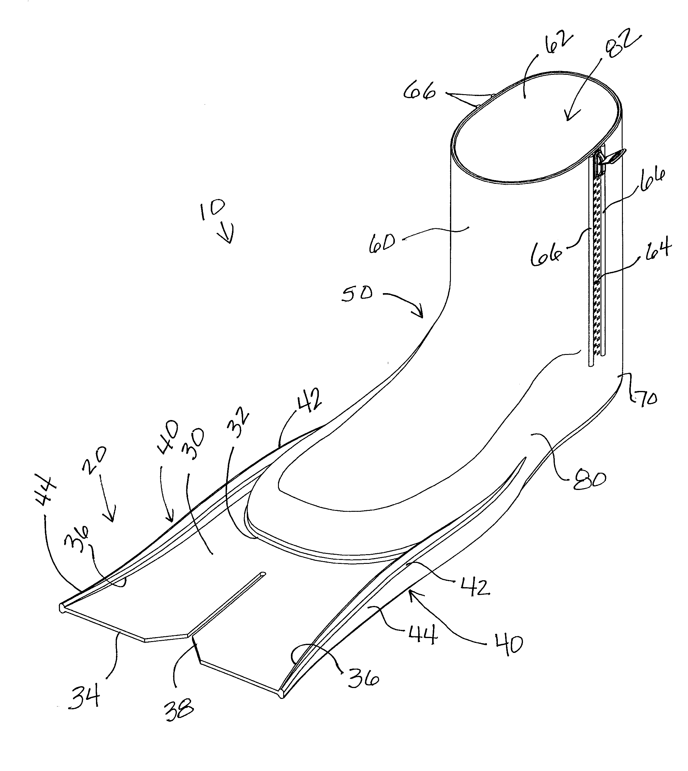
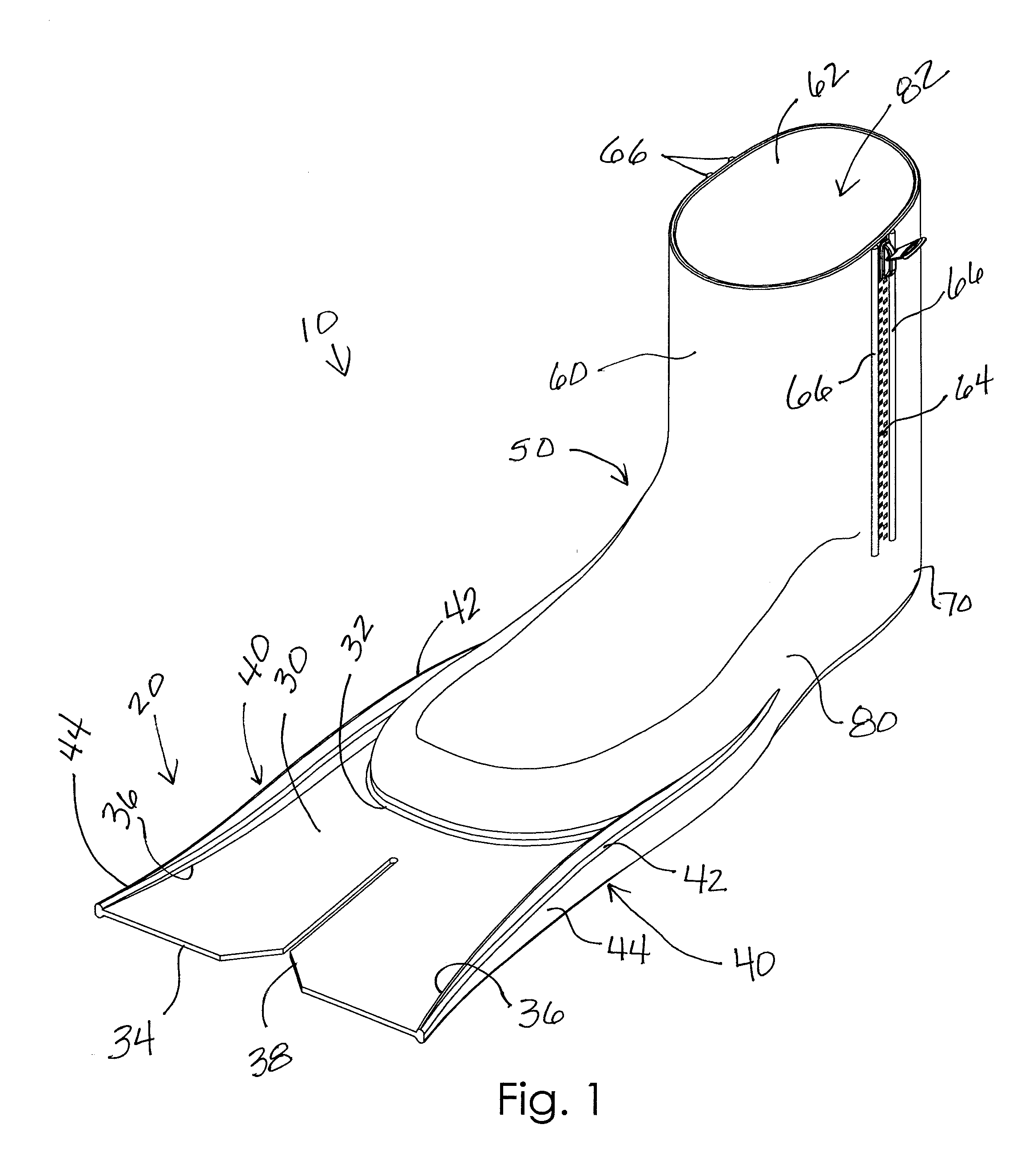
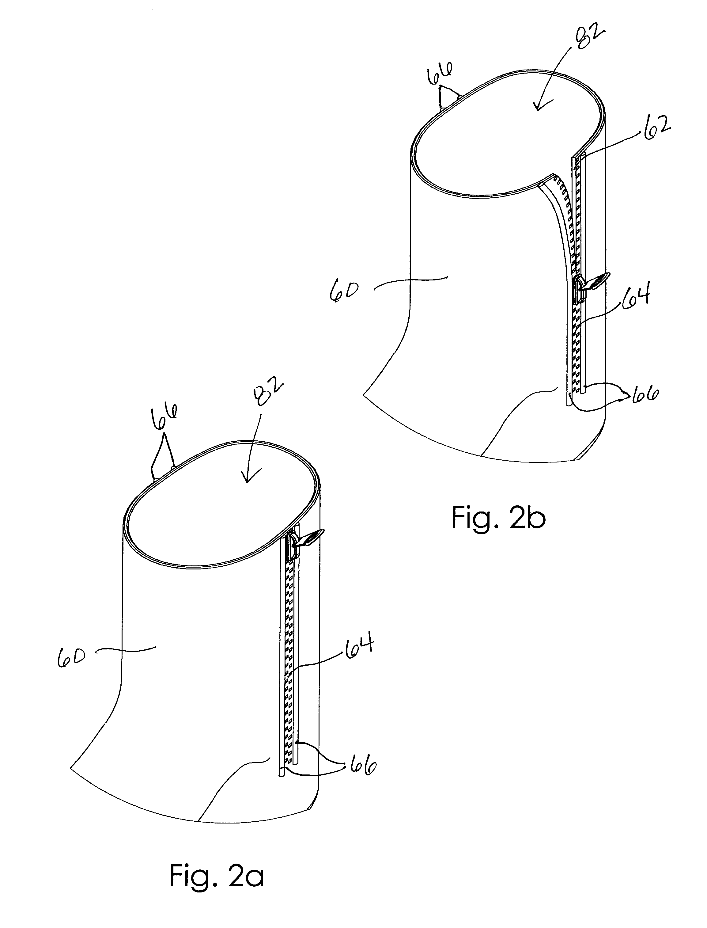
[0023]A swim fin boot will now be described in detail with reference to FIGS. 1 to 3c of the accompanying drawings. The swim fin boot 10 includes a fin portion 20 having a body member 30 and opposed side rails 40. The swim fin boot 10 further includes a boot member 50 having an ankle portion 60, heel portion 70, and foot portion 80, the boot member 50 being connected to the fin portion 20 in a unitary construction.

[0024]Now with specific reference to the drawings, the body member 30 of the fin portion 20 essentially is the webbing used for propelling a wearer through the water and may also be referred to generally herein as the ‘fin.” The body member 30 may include a generally flat construction or it may have various relief features (such as nubs, recesses, channels, or the like) intended to alter the way the body member 30 cuts through or pushes water during use. The body member 30 spans between the opposed side rails 40 as described below and includes opposed proximal 32 and dista...


PUM


Abstract

A swim fin boot includes a fin portion having a body member and a pair of opposed side rails, each side rail including an extension segment connected to a proximal end of the body member and extending away therefrom, respective extension segments being spaced apart from and parallel to one another. Each side rail includes a boundary segment connected to body portion peripheral edges, the body portion extending between the side rail boundary segments. A boot member includes an ankle portion defining an open top configured to selectively receive insertion of a person's foot. The boot member includes a foot portion connected to a lower end of the ankle portion defining an interior cavity configured to receive the person's foot when inserted into the ankle portion, the foot portion being connected to respective side rail extension segments such that the fin portion and the boot member have a unitary construction.

Description

CROSS REFERENCE TO RELATED APPLICATIONS[0001]This application relates to and claims the benefit of a previously filed U.S. Provisional Patent Application Ser. No. 61 / 398,252 filed Jun. 21, 2010, and entitled Swim Fin with Ankle Bootie.BACKGROUND OF THE INVENTION[0002]The invention relates generally to footwear that may be used for assisting propulsion in various water-bound personal sport activities and, more particularly, to water propulsion footwear that has an ankle portion so as to secure the footwear to the user's foot and ankle more firmly.[0003]Devices to aid a person in propelling or otherwise assisting a person move in water, such as diving, swimming, surfing, body boarding and the like, are popular and desirable to improve a user's performance. Propulsion devices are well known in water-bound personal sport activities and may include various bladed foot attachments, such as swim fins. Swim fins provide a portable means for aided propulsion that are easy to store, generally...

Claims


Application Information

Patent Timeline
Patent Type & Authority Applications(United States)
IPC IPC(8): A63B31/11
CPCA63B31/11
Inventor MONTEMURRO, DAVID
Owner MONTEMURRO DAVID
Learn More