
Supporting arm assembly for a display

a technology for supporting arms and displays, applied in the direction of machine supports, instruments, cabinet/cabinet/drawer covers, etc., can solve the problems of time-consuming and laborious reattaching the display to the conventional supporting arm, time-consuming and laborious detachment of the display from the supporting arm for repair, etc., to achieve convenient and convenient detachment

Active Publication Date: 2011-12-29
MODERNSOLID INDAL
View PDF16 Cites 99 Cited by
  • Summary
  • Abstract
  • Description
  • Claims
  • Application Information

AI Technical Summary

Benefits of technology

[0006]The main objective of the invention is to provide a supporting arm assembly for a display and having a capability of easily and conveniently detaching the display from the supporting arm.

Problems solved by technology

However, the conventional supporting arm is connected securely with the display with fasteners, so to detach the display from the supporting arm for repair is time consuming and laborious.
Additionally, to reattach the display onto the conventional supporting arm is also time consuming and laborious.

Method used


Image

  • Supporting arm assembly for a display
  • Supporting arm assembly for a display
  • Supporting arm assembly for a display

Examples


Embodiment Construction

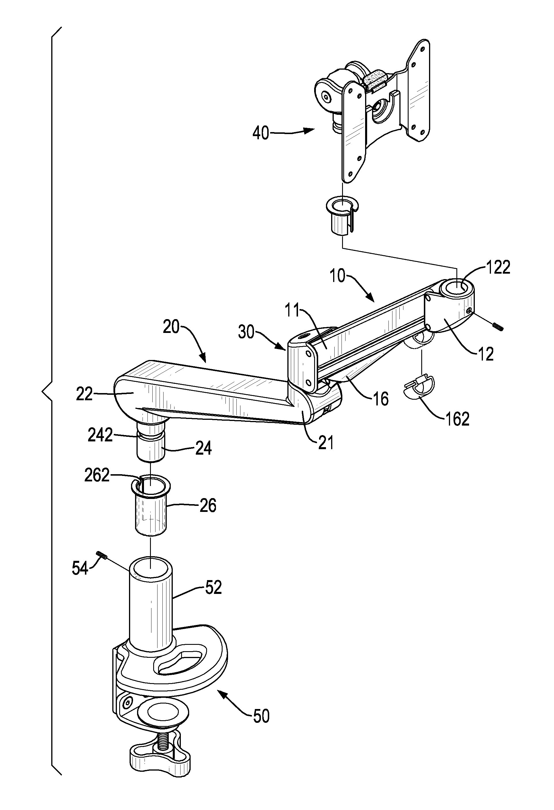
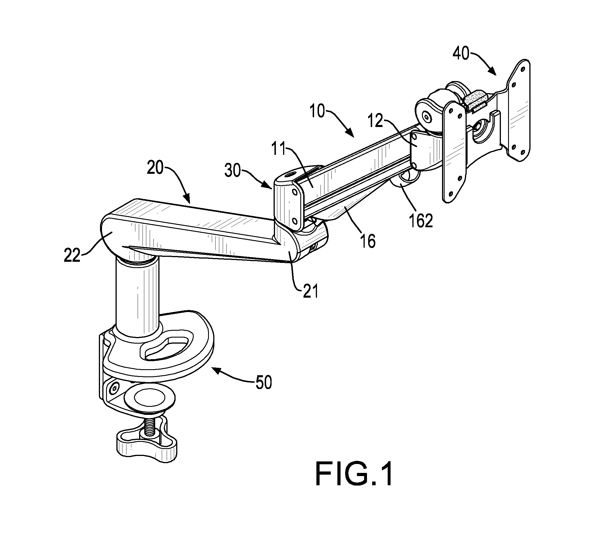
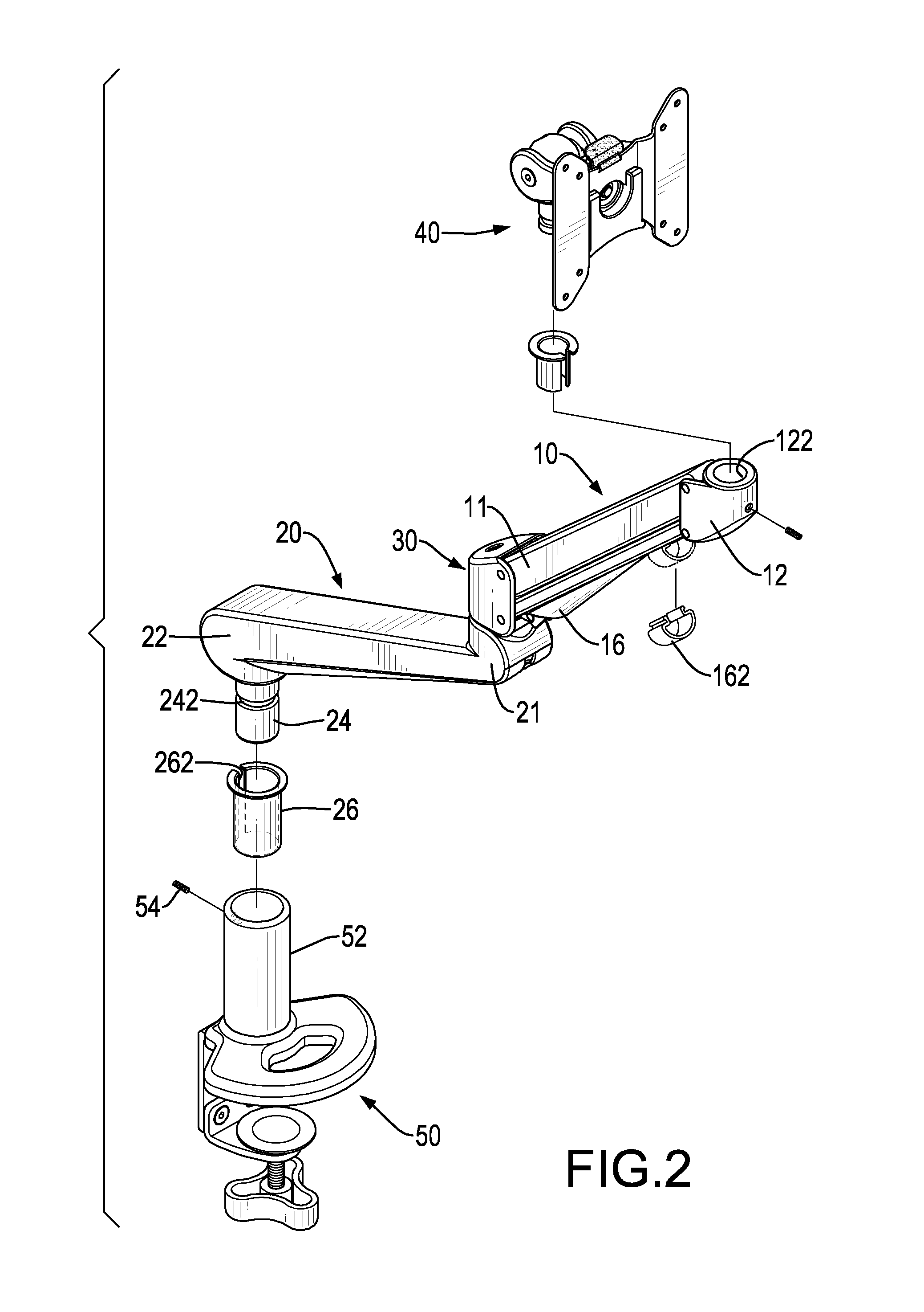
[0020]With reference to FIGS. 1 and 2, a supporting arm assembly for a display in accordance with the present invention comprises an upper arm 10, a lower arm 20, a display-connecting device 40 and a holding base 50. The upper and lower arms 10,20 are connected pivotally with each other, such that the relative angle / position between the arms 10,20 can be adjusted. The display-connecting device 40 is mounted on the upper arm 10 at an end opposite to the lower arm 20 and is connected with the display. The holding base 50 is mounted on the lower arm 20 at an end opposite to the upper arm 10 and is mounted securely on a fixing object, such as a table, a wall or a ceiling. Accordingly, the display can be held or hung on the fixing object by the supporting arm.

[0021]The upper arm 10 is elongated and has two ends. The end of the upper arm 10 connected to the lower arm 20 is defined as a pivotal end 11, and the end of the upper arm 10 on which the display-connecting device 40 is mounted is ...


PUM


Abstract

A supporting arm assembly has an upper arm, a lower arm, a display-connecting device and a holding device. The lower arm is pivotally connected to the upper arm. The display-connecting device is mounted on the upper arm and has a pivotal pin, a connecting base, a display mount, an engaging panel and a display holding panel. The pivotal pin is mounted rotatably on the upper arm. The connecting base is connected pivotally to the pivotal pin. The display mount is mounted securely on the connecting base. The engaging panel is mounted in the display mount. The display holding panel is mounted detachably in the display mount and detachably engages the engaging panel by an engagement between at least one engaging protrusion and at least one engaging recess. The holding base is mounted on the lower arm at an end opposite to the upper arm.

Description

BACKGROUND OF THE INVENTION[0001]1. Field of the Invention[0002]The present invention relates to a supporting arm assembly, and more particularly to a supporting arm assembly for a display and having a capability of easily and conveniently detaching the display from the supporting arm.[0003]2. Description of Related Art[0004]A conventional supporting arm is connected securely to a fixing object, such as a table, a wall or a ceiling and is connected to a display to hold or hang the display onto the fixing object. However, the conventional supporting arm is connected securely with the display with fasteners, so to detach the display from the supporting arm for repair is time consuming and laborious. Additionally, to reattach the display onto the conventional supporting arm is also time consuming and laborious.[0005]To overcome the shortcomings, the present invention tends to provide a supporting arm for a display to mitigate or obviate the aforementioned problems.SUMMARY OF THE INVENT...

Claims


Application Information

Patent Timeline
IPC IPC(8): F16M13/00
CPCF16M11/041F16M11/105F16M11/2064F16M11/2092F16M2200/068F16M13/022F16M2200/063F16M2200/065F16M11/24F16M11/10F16M11/2014
Inventor HUNG, CHIN-JUI
Owner MODERNSOLID INDAL
Learn More