

Spark plug
a technology of spark plugs and spark plugs, applied in the field of spark plugs, can solve the problems of deteriorating spark endurance, separation of noble metal tips, and welding strength failing to cope with severe operating conditions
- Summary
- Abstract
- Description
- Claims
- Application Information
AI Technical Summary
Benefits of technology
Problems solved by technology
Method used
Image

Examples
first embodiment
A. First Embodiment
A1. Structure of Spark Plug:
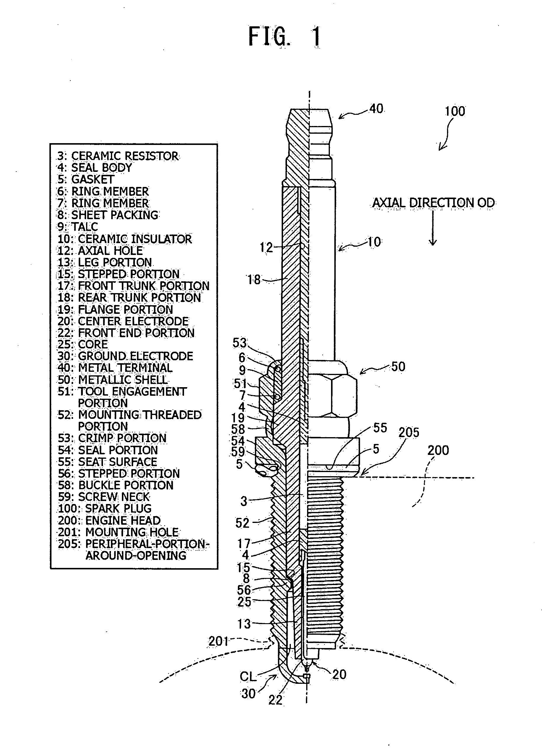
[0063]FIG. 1 is a partially sectional view showing a spark plug 100 according to an embodiment of the present invention. In the following description, an axial direction OD of the spark plug 100 in FIG. 1 is referred to as the vertical direction, and the lower side of the spark plug 100 in FIG. 1 is referred to as the front side of the spark plug 100, and the upper side as the rear side.
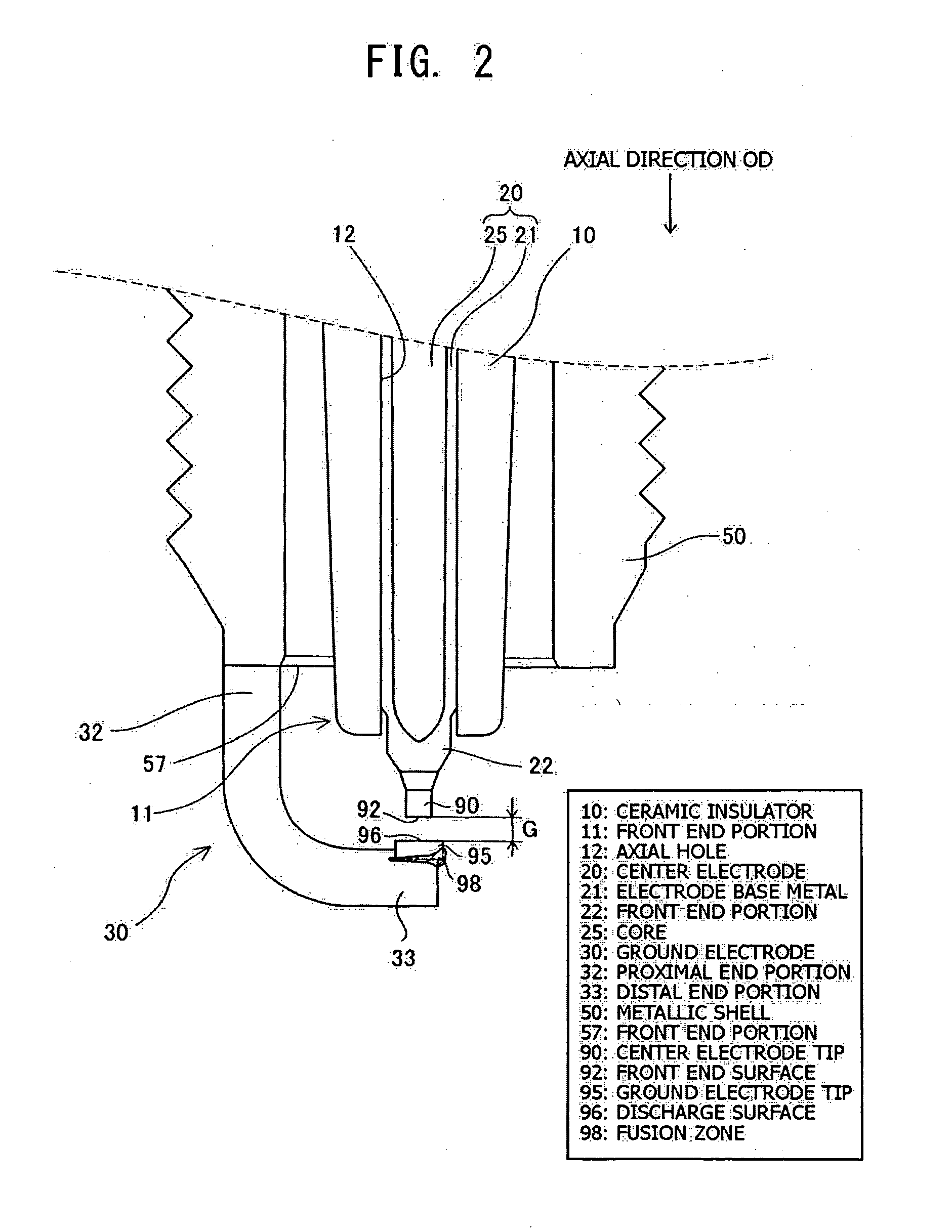
[0064]The spark plug 100 includes a ceramic insulator 10, a metallic shell 50, a center electrode 20, a ground electrode 30, and a metal terminal 40. The center electrode 20 is held in the ceramic insulator 10 while extending in the axial direction OD. The ceramic insulator 10 functions as an insulator. The metallic shell 50 holds the ceramic insulator 10. The metal terminal 40 is provided at a rear end portion of the ceramic insulator 10. The construction of the center electrode 20 and the ground electrode 30 will be described in detail later with refer...
second embodiment
B. Second Embodiment
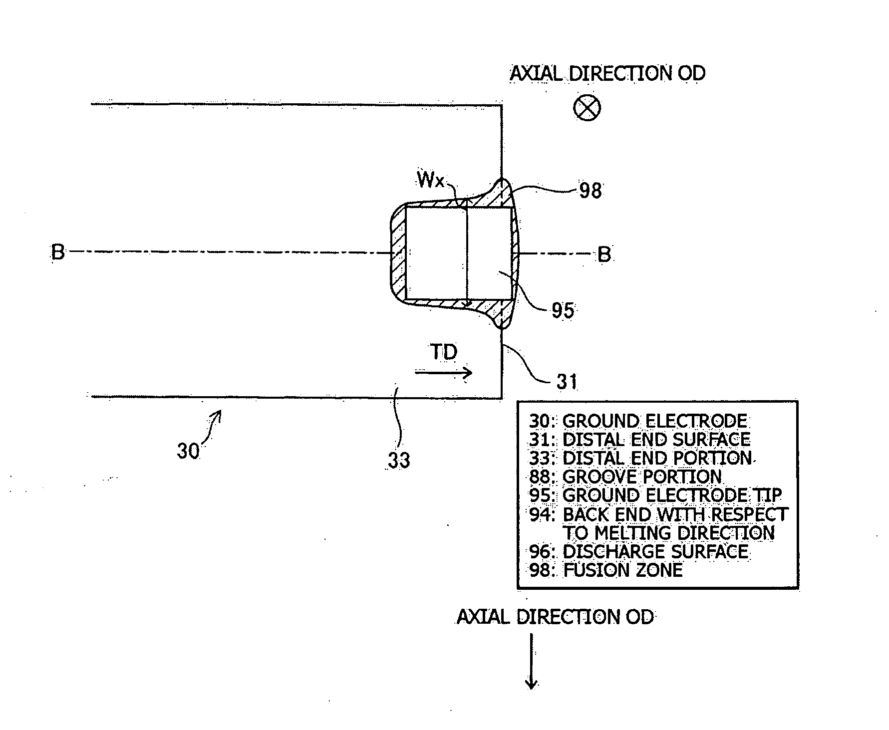
[0087]FIG. 4 is an explanatory view showing the sectional shape of a fusion zone 98b of a spark plug 100b according to a second embodiment of the present invention. Preferably, at least a portion of the ground electrode tip 95 is fitted in the groove portion 88 formed in the ground electrode 30, and the fusion zone 98b is also formed at such a portion 97 (the boundary 97) of a region between the groove portion of the ground electrode 30 and the ground electrode tip 95 that is substantially perpendicular to the discharge surface 96 of the ground electrode tip 95. Since, through employment of such the feature, the ground electrode tip 95 and the ground electrode 30 can be welded via the fusion zone 98b along a wider portion of the boundary (i.e., interface) therebetween, the welding strength between the ground electrode tip 95 and the ground electrode 30 can be further enhanced.
[0088]The fusion zone 98b having such a shape can be formed by increasing the time of ra...
third embodiment
C. Third Embodiment
[0089]FIG. 5 is an explanatory view showing the sectional shape of a fusion zone 98c of a spark plug 100c according to a third embodiment of the present invention. Preferably, as shown in FIG. 5, half or more of the boundary 45 between the ground electrode tip 95 and a portion of the fusion zone 98c formed on a side opposite the surface 96 (the discharge surface 96) of the ground electrode tip which faces the center electrode 20 is in parallel with the discharge surface 96 of the ground electrode tip 95. Since employment of such the feature increases the volume of such a portion of the ground electrode tip 95 that is not melted by a fiber laser beam or the like, resistance to spark-induced erosion can be improved.
[0090]The fusion zone 98c having such a shape can be formed through radiation of a fiber laser beam or an electron beam toward the boundary between the ground electrode 30 and the ground electrode tip 95 from a direction BD oblique to the boundary.
PUM
 Abstract
Description
Claims
Application Information