Linear chromatic confocal microscopic system

Active Publication Date: 2012-01-26
NAT TAIPEI UNIV OF TECH
View PDF2 Cites 76 Cited by
  • Summary
  • Abstract
  • Description
  • Claims
  • Application Information

AI Technical Summary

Benefits of technology

[0006]The present invention provides a linear chromatic confocal microscopic system having two corresponding optical fiber modules, wherein one optical fiber module is adopted to guide a light to project onto an object while the other optical fiber module is adopted to receive an object light reflected from the object. Since the optical fiber module for receiving the object light has a plurality of optical fibers, and each optical fiber performs a spatia

Problems solved by technology

Since the conventional chromatic confocal microscopic systems are generally bulky, the space occupied by them may induce inaccessibility or difficulties for in-situ inspection or measurement.
Further, if the inclination angle of the object surface is large, or the measurement space is limited, the optical measurement performance achieved by the conventional desktop-type chromatic confocal microscopic system may be significantly limited.
For example, if it is required to measure a bump 3-D profile formed o

Method used


Image

  • Linear chromatic confocal microscopic system
  • Linear chromatic confocal microscopic system
  • Linear chromatic confocal microscopic system

Examples


Embodiment Construction

[0029]For your esteemed members of reviewing committee to further understand and recognize the fulfilled functions and structural characteristics of the disclosure, several exemplary embodiments cooperating with detailed description are presented as follows.

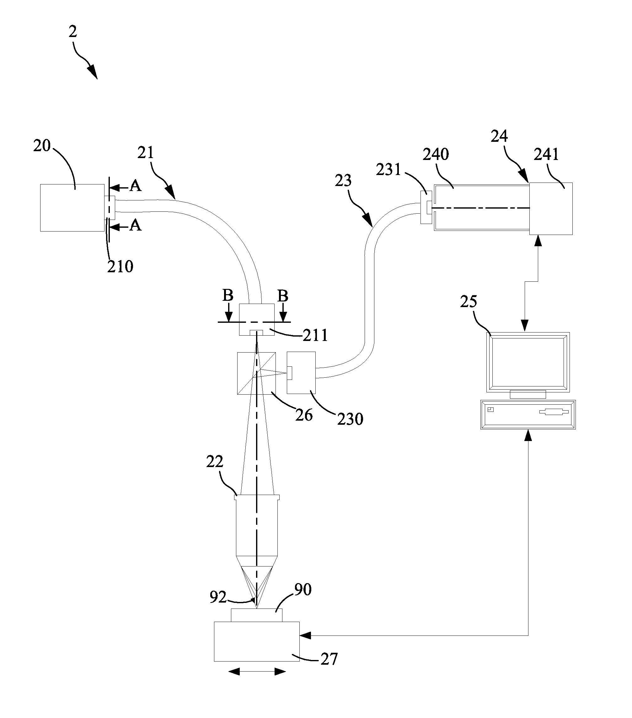
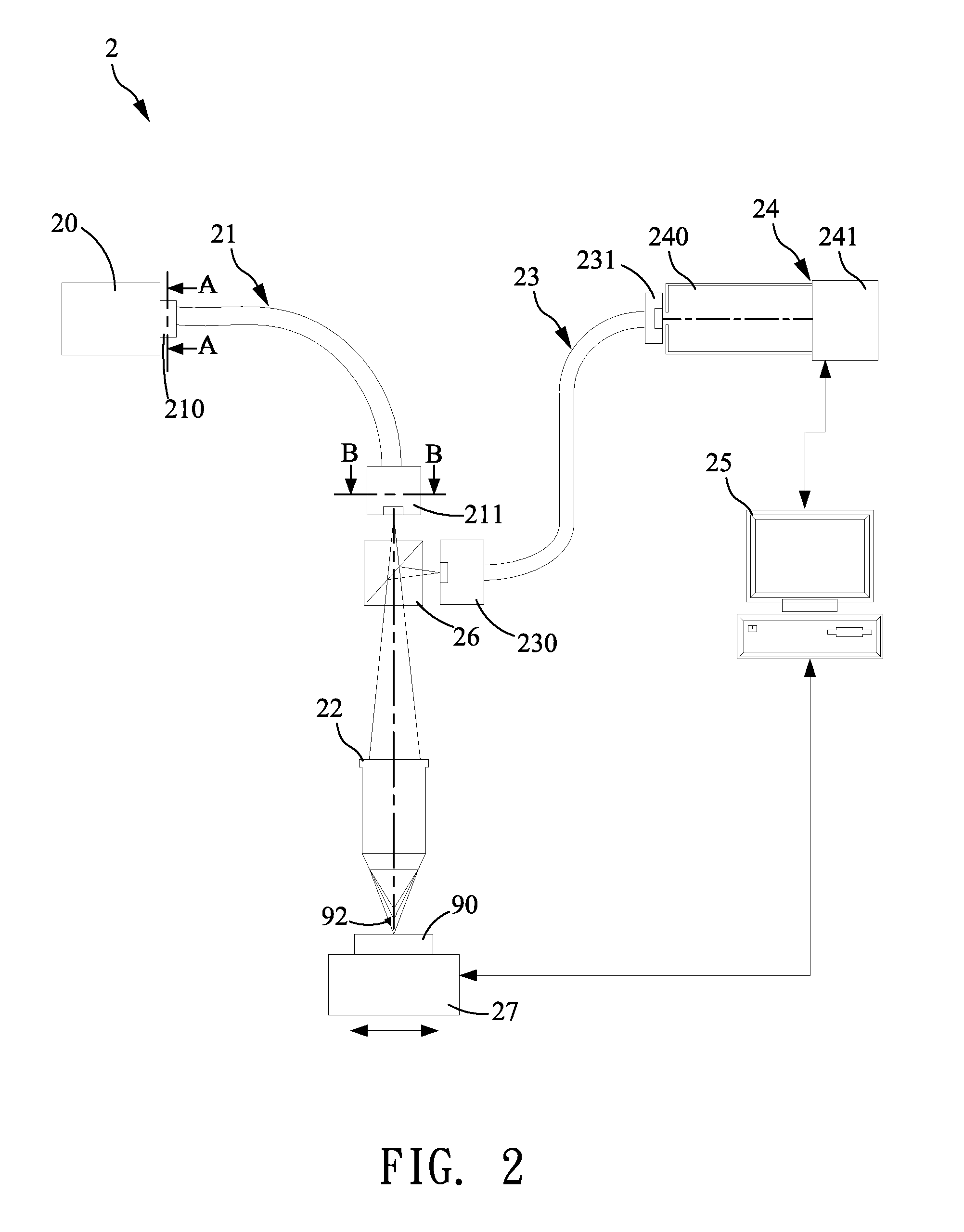
[0030]Please refer to FIG. 2, which illustrates an embodiment of the linear chromatic confocal microscopic system according to the present invention. The system 2 comprises a light source 20, a first optical fiber module 21, a chromatic dispersion objective 22, a second optical fiber module 23, a spectrum image sensing unit 24, and an operation processing unit 25. The light source 20 provides a detecting light, wherein, in the present embodiment, the light source 20 is a broadband light source for generating a broadband light beam having different wavelengths.

[0031]The first optical fiber module 21 has a first end and a second end, wherein the first end is coupled with the light source 20, and the second end modulates the detecti...


PUM


Abstract

The present invention provides a chromatic confocal microscopic system in which two conjugate fiber modules are spatially configured and employed to conduct a detecting light from a light source and an object light reflected from an object, respectively. By means of the two spatially corresponding fiber modules, the detecting light is projected on the object and the reflected light from the object is entered into the other fiber module. Since each fiber of the fiber module is capable of filtering out the unfocused light and stray lights and allowing the focused light pass therethrough a line slit, thereby minimizing potential interference from light cross talk caused by the overlapped light spots, not only can the present invention obtain the information of surface profile of the object with high vertical measurement resolution, but also achieve high lateral resolution during confocal measurement.

Description

FIELD OF THE INVENTION[0001]The present invention relates to a confocal microscopic technology, and, more particularly, to a linear chromatic confocal microscopic system.BACKGROUND OF THE INVENTION[0002]Conventional chromatic confocal microscopic system is generally disposed on a desktop for inspecting a surface profile of an object by performing a vertical or translational scanning. Since the conventional chromatic confocal microscopic systems are generally bulky, the space occupied by them may induce inaccessibility or difficulties for in-situ inspection or measurement. Further, if the inclination angle of the object surface is large, or the measurement space is limited, the optical measurement performance achieved by the conventional desktop-type chromatic confocal microscopic system may be significantly limited. For example, if it is required to measure a bump 3-D profile formed on a large-size wafer, due to the limitation of desk-type chromatic confocal microscopic system, it w...

Claims


Application Information

Patent Timeline
IPC IPC(8): G01J3/40
CPCG01B2210/50G02B21/0064G02B21/006G02B21/0032
Inventor CHEN, LIANG-CHIAWU, YONG-LINCHANG, YI-WEI
Owner NAT TAIPEI UNIV OF TECH
Why Eureka
Try Eureka