Electronic device assembly

a technology of electronic devices and components, applied in the direction of electrical apparatus construction details, electrical apparatus casings/cabinets/drawers, instruments, etc., can solve the problems of power waste and inability to automatically turn off the power supply of electronic devices

Inactive Publication Date: 2012-02-09
HON HAI PRECISION IND CO LTD
View PDF3 Cites 918 Cited by
  • Summary
  • Abstract
  • Description
  • Claims
  • Application Information

AI Technical Summary

Problems solved by technology

However, the power supplied to the electronic device cannot be automatically turned off when accommoda

Method used


Image

  • Electronic device assembly
  • Electronic device assembly
  • Electronic device assembly

Examples


Embodiment Construction

[0011]The disclosure is illustrated by way of example and not by way of limitation in the figures of the accompanying drawings in which like references indicate similar elements. It should be noted that references to “an” or “one” embodiment in this disclosure are not necessarily to the same embodiment, and such references mean at least one.

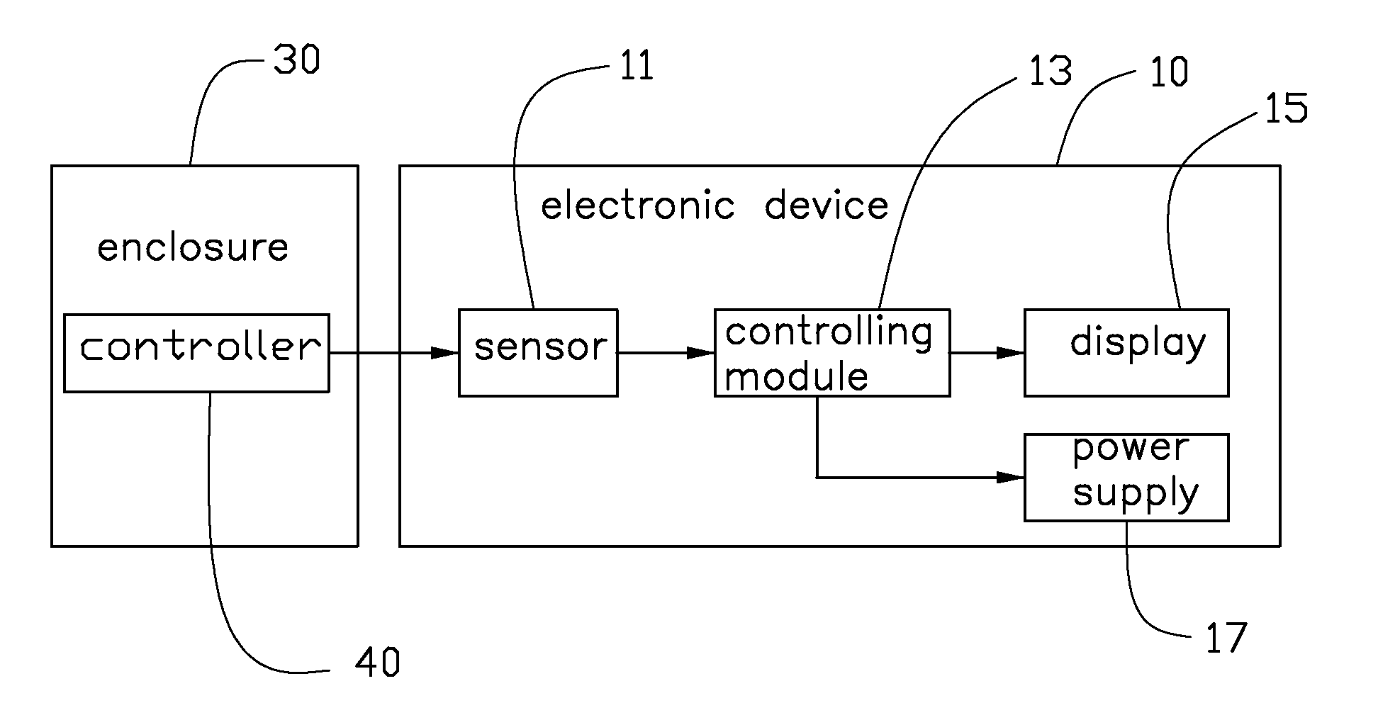
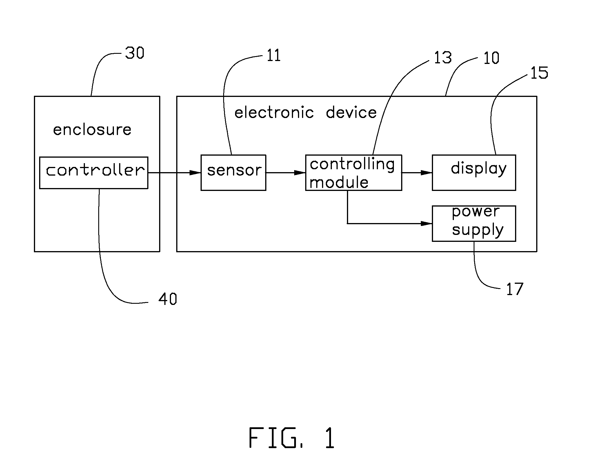
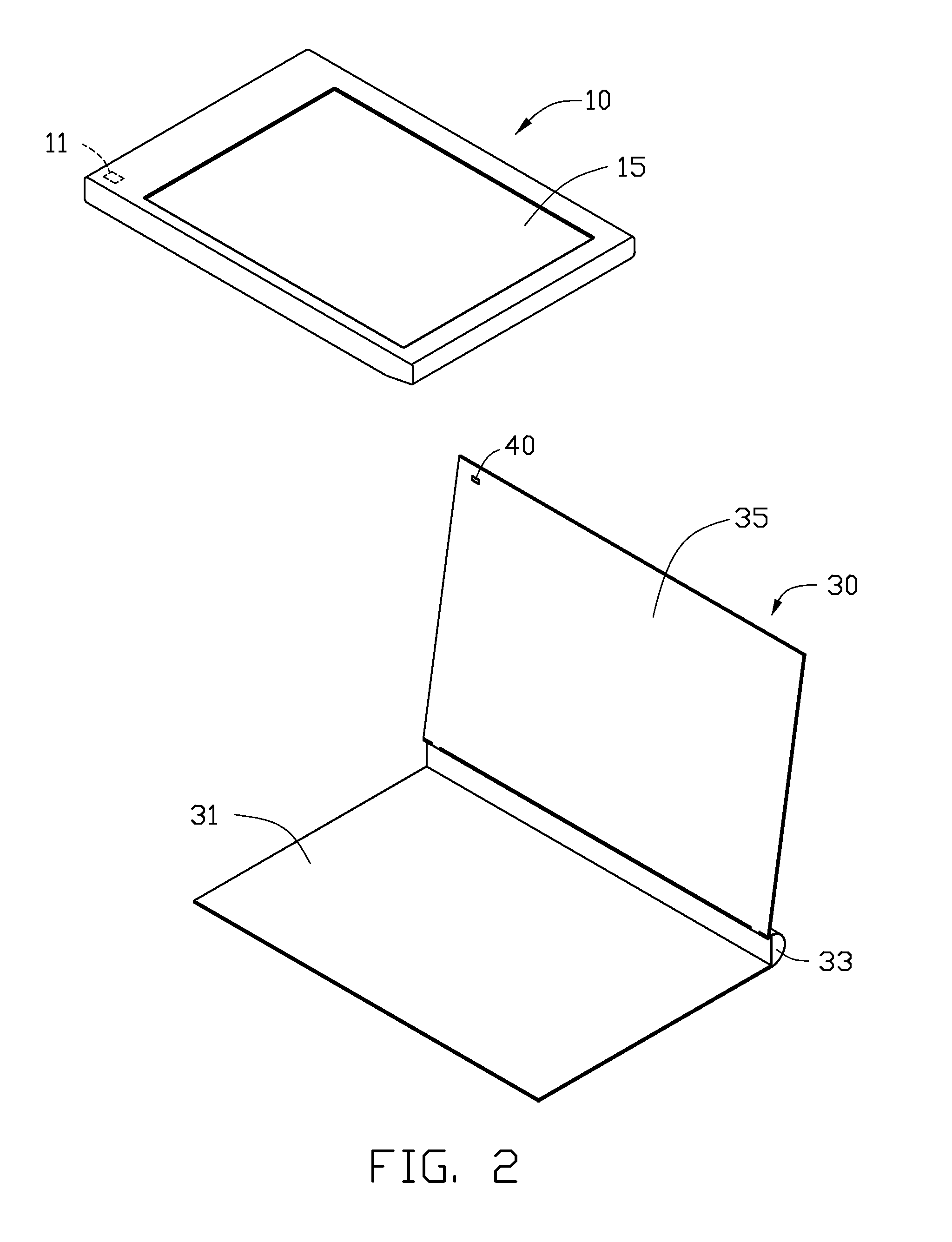
[0012]Referring to FIGS. 1 and 2, an electronic device assembly in accordance with an embodiment includes an electronic device 10 and an enclosure 30 configured for receiving the electronic device 10. In one embodiment, the electronic device 10 may be, for example, a mobile phone or a personal digital assistant.

[0013]The electronic device 10 includes a display 15 for displaying information and a power supply 17 for supplying power to the electronic device 10. A sensor 11 and a controlling module 13 are disposed in the electronic device 10. The controlling module 13 is electronically connected to the sensor 11. The sensor 11 can transmit signals t...


PUM


Abstract

An electronic device assembly includes an electronic device and an enclosure receiving the electronic device. The electronic device includes a display and a sensor. The enclosure includes a cover and a controller attached to the cover. The cover is rotatable relative to the electronic device between a first position and a second position. In the first position, the cover covers the electronic device, and the controller controls the sensor transmitting a first signal to the electronic device, for turning off a power supplied to the display. In the second position, the electronic device is exposed, and the controller controls the sensor transmitting a second signal to the electronic device, for turning on the power of the display.

Description

BACKGROUND[0001]1. Technical Field[0002]The present disclosure relates to electronic device assemblies, more particularly an electronic device assembly, which automatically controls the power supply to a display of the electronic device assembly.[0003]2. Description of Related Art[0004]Nowadays, electronic devices, such as mobile phones, and personal digital assistants, are in high demand. Usually, the electronic device is accommodated in an enclosure for preventing damage. However, the power supplied to the electronic device cannot be automatically turned off when accommodated in the enclosure if the electronic device is not used for some time, so the power is often wasted.BRIEF DESCRIPTION OF THE DRAWINGS[0005]Many aspects of the embodiments can be better understood with references to the following drawings. The components in the drawings are not necessarily drawn to scale, the emphasis instead being placed upon clearly illustrating the principles of the embodiments. Moreover, in ...

Claims


Application Information

Patent Timeline
IPC IPC(8): H05K7/00
CPCG06F1/1626G06F1/3206Y02B60/1242G06F2200/1633G06F1/3265Y02D10/00
Inventor HSU, PO-YEN
Owner HON HAI PRECISION IND CO LTD
Why Eureka
Try Eureka