Cable slider with symmetric pieces

Active Publication Date: 2012-02-23
PRODN RESOURCE GROUP L L C
View PDF24 Cites 16 Cited by
  • Summary
  • Abstract
  • Description
  • Claims
  • Application Information

AI Technical Summary

Problems solved by technology

This can be cumbersome since these existing chain sliders are often changed out by stagehands while they are installed high up on trusses, lifts, or ladders where loose tools and parts are a hazard.

Method used


Image

  • Cable slider with symmetric pieces
  • Cable slider with symmetric pieces
  • Cable slider with symmetric pieces

Examples


second embodiment

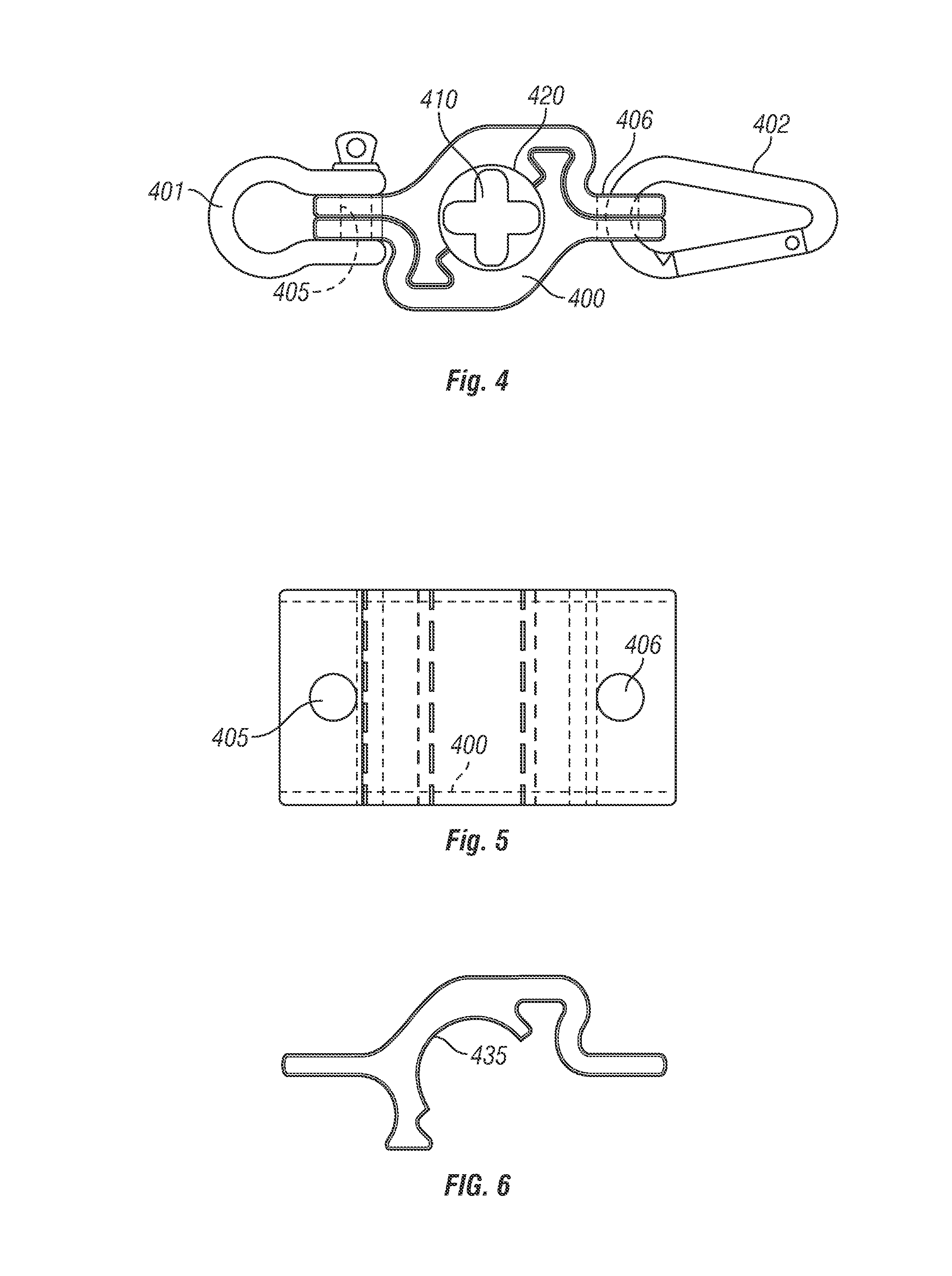
[0022]A second embodiment, shown in FIGS. 4-6 shows a chain slider that allows movement along a chain rather than along the cable as in the embodiment of FIG. 1 through 3. In this embodiment, the cable piece 400 includes a circular center hole 420, large enough to hold a chain, shown in cross-section as a plus shape 410. In this embodiment, the device may be controlling for example a chain motor with a lift chain. The chain motor has an electrical connection with an electrical cable. The slider 420 passively slides up and down the chain 410 due to tension / slack on the electrical cable as the chain motor moves.

first embodiment

[0023]As in the first embodiment, the chain portion 400 forms a central body which is connected at one end to a fixed portion 401 that connects together with the screw, and is connected at the other end to a freely pivotable portion 402 formed of a carabiner. The part 401 does not pivot, so loads attached at the part 401 cannot cause the part 401 to pivot. Loads attached at the 402 end, however, do cause that end to pivot.

[0024]FIG. 5 shows a front view of the device, showing the center portion 400, the hole 405 through which the first end 401 is attached and the hole 406 through which the second end is attached.

[0025]As in the first embodiment, FIG. 6 shows how the center portion in the second embodiment is formed from two symmetrical pieces.

third embodiment

[0026]A third embodiment, shown in FIGS. 7-9, is a nonrotating model, which does not allow the chain to rotate. In this embodiment, the center portion 700 has a substantially plus shaped central portion 710 which is captured around the chain end to rotate with the chain; so that if the chain rotates, which is rare, the device also rotates. As in the other embodiments, a first end 720 includes a non-rotatable holder, that is attached through a through hole 721 by a screw 722. The second end includes a rotatable carabiner 730 which is attached through the through hole 731, and can freely rotate in any desired direction. FIG. 8 shows a front view of the center portion 700, showing the holes 721 and 731. As in the other embodiments, the center portion is symmetrical, so that either side can attach to either the fixed portion or the pivotable portion.

[0027]FIG. 9 shows a single plate 701 which is a symmetrical plate forming the portions.

[0028]Each of these embodiments have the advantage ...


PUM

PropertyMeasurementUnit
distanceaaaaaaaaaa
diameteraaaaaaaaaa
sizeaaaaaaaaaa

Abstract

a device which can slide up and down on a chain or cable, can be loosened to attach to the chain or cable, but does not have any parts that come free when the part is loosened.

Description

[0001]This application claims priority from provisional application No. 61 / 374,553, filed Aug. 17, 2010, the entire contents of which are herewith incorporated by reference.BACKGROUND[0002]For concert tours, industrial shows, and Broadway shows, it has become common to festoon electrical cables vertically up tensioned moving chain hoist chains and which wire ropes.[0003]Existing plastic chain / cable sliders are two piece units joined with multiple fasteners and requiring tools for installation or removal. This can be cumbersome since these existing chain sliders are often changed out by stagehands while they are installed high up on trusses, lifts, or ladders where loose tools and parts are a hazard.SUMMARY OF THE INVENTION[0004]The new embodiment forms a chain / cable slider that has two matching halves that dovetail together with no tools or loose fasteners.BRIEF DESCRIPTION OF THE DRAWINGS[0005]FIG. 1 shows a plan view according to an embodiment of an assembled device according to t...

Claims


Application Information

Patent Timeline
Patent Type & Authority Applications(United States)
IPC IPC(8): F16G15/00F16G11/00F16B1/00
CPCH02G1/06Y10T403/7152H02G11/00F16G11/00F16G15/04F16G15/06Y10T403/7094Y10T24/39Y10T403/65Y10T24/3902Y10T403/655Y10T403/61Y10T29/4984Y10T24/45267H02G3/30F16B2200/30
Inventor KEMPF, JAMES
Owner PRODN RESOURCE GROUP L L C
Why Eureka
Try Eureka