
Hook meter with improved illumination

a technology of hook meter and illumination, applied in the field of hook meter, can solve the problem of affecting the illumination effect of the prior art and achieve the effect of improving the illumination effect and the convenience of the tool

Inactive Publication Date: 2012-03-01
CHUNG INSTR ELECTRONICS IND
View PDF13 Cites 0 Cited by
  • Summary
  • Abstract
  • Description
  • Claims
  • Application Information

AI Technical Summary

Benefits of technology

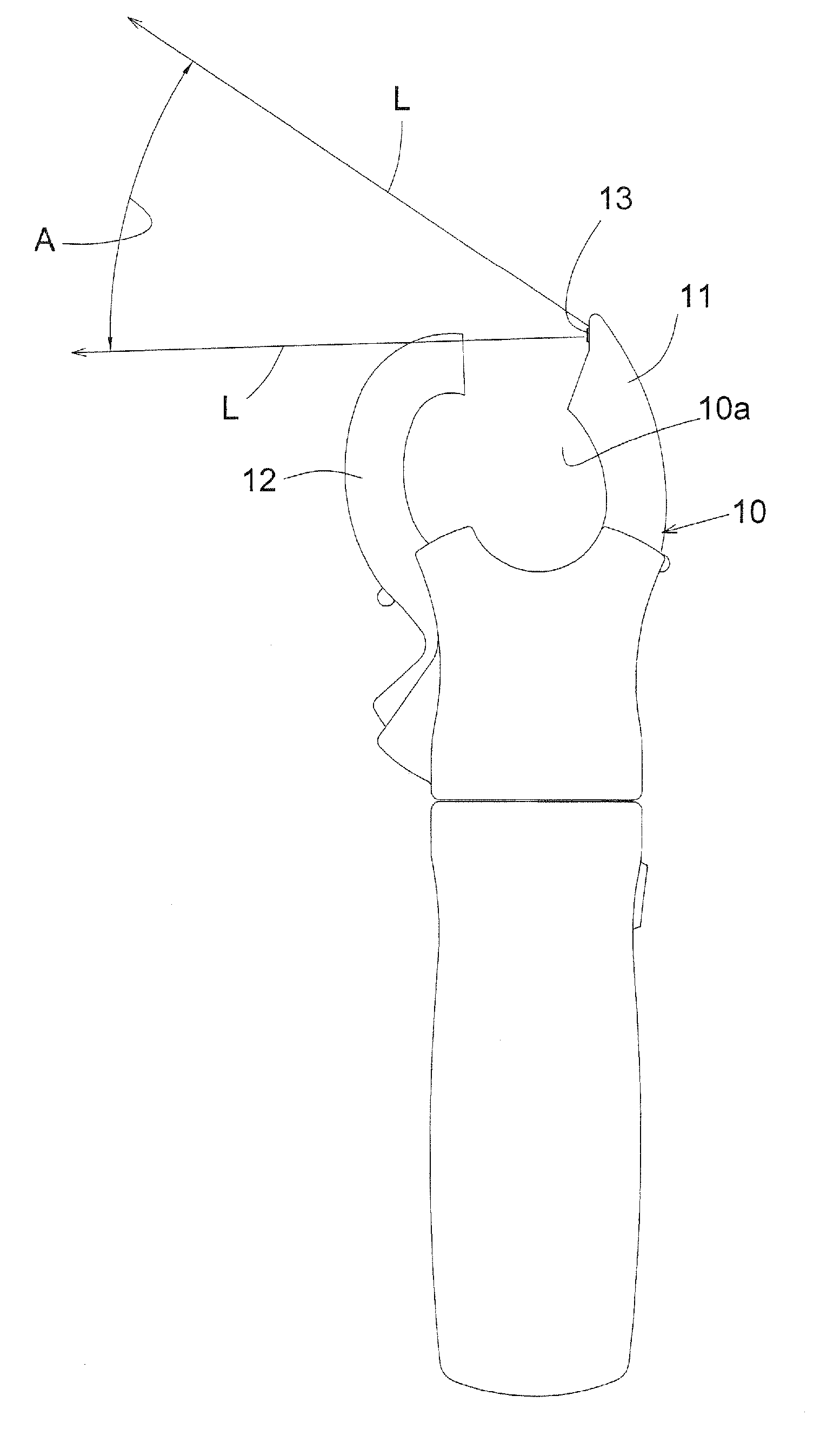
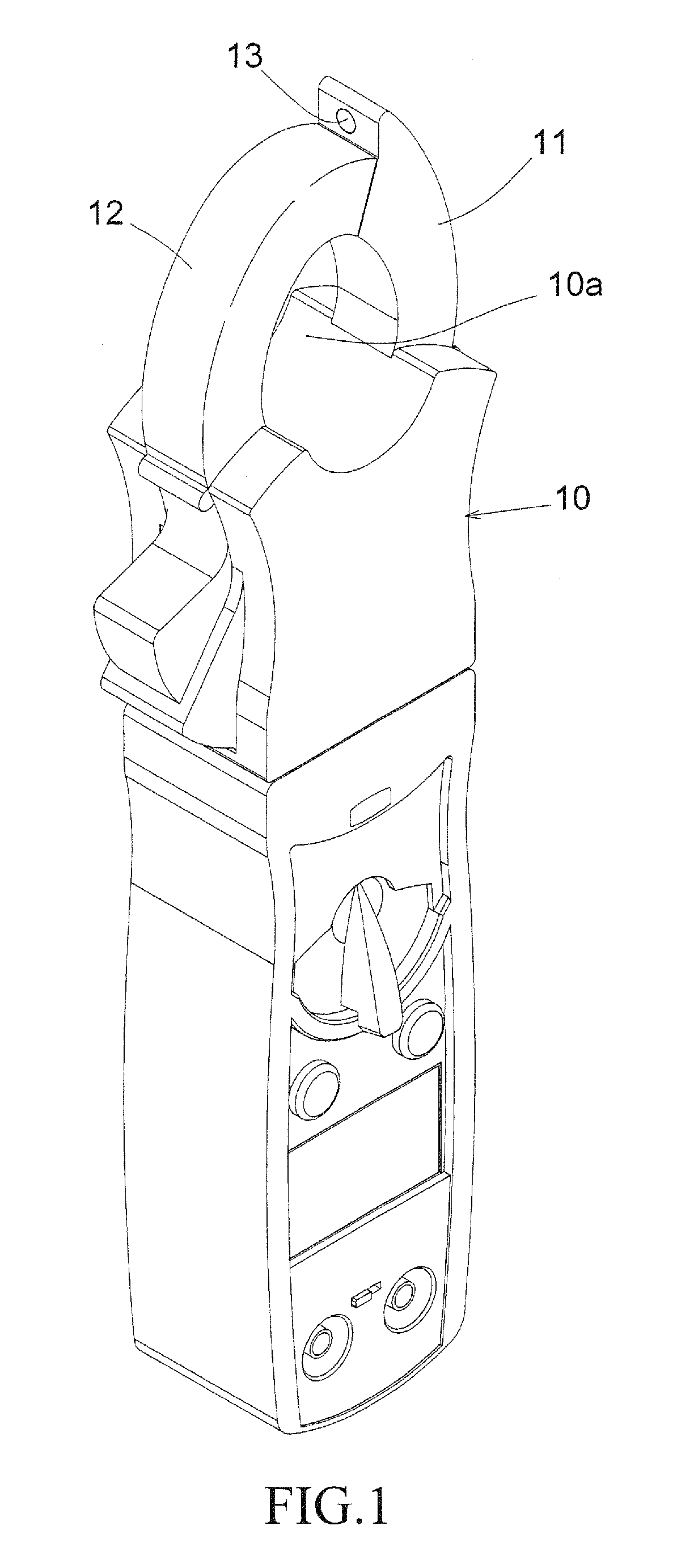
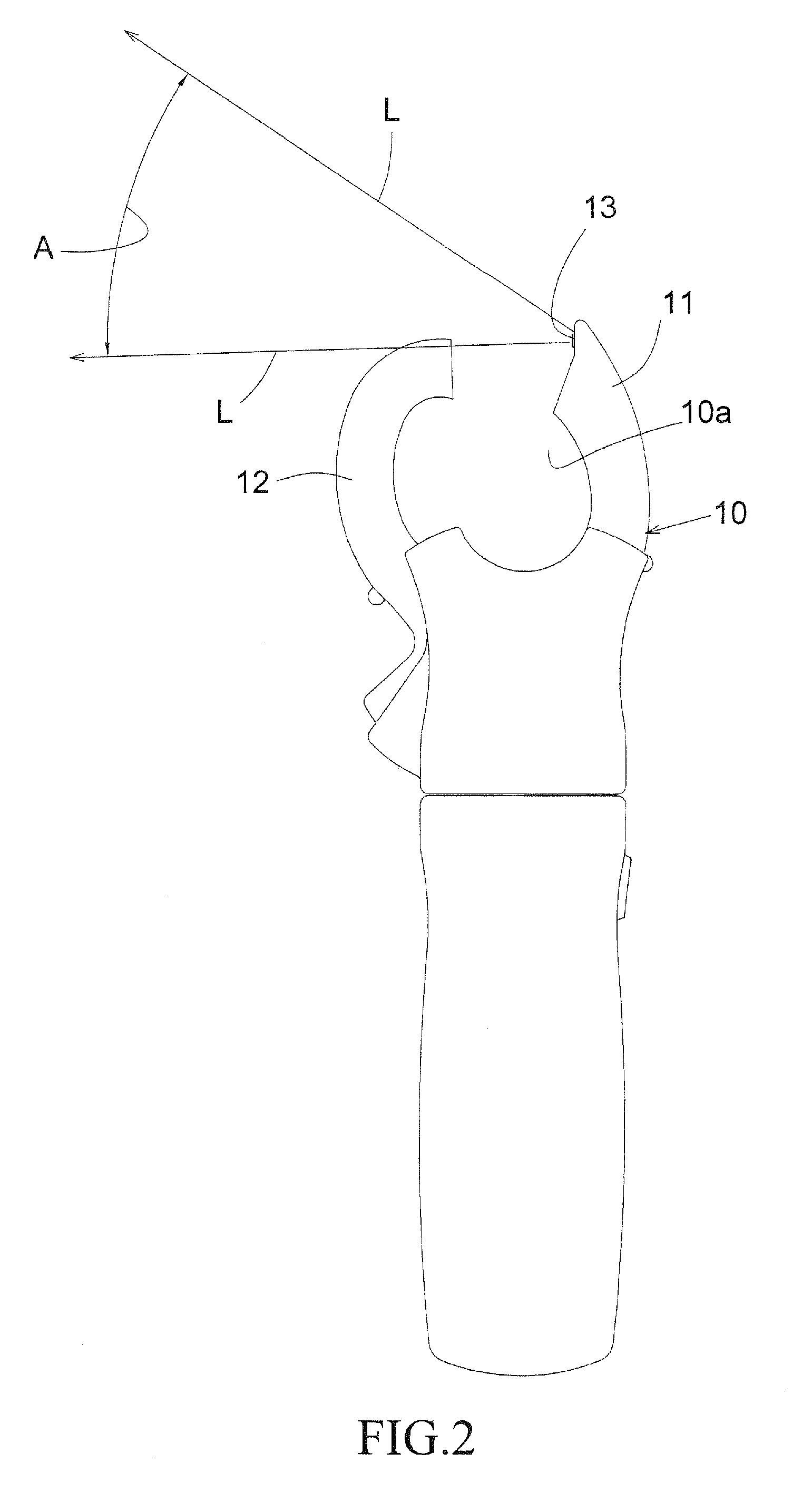
[0004]A hook meter according to the present invention contains a body member, a static arm, a moveable arm, both extended from a front end of the body member. The static and moveable arms are shaped so that each has a side surface rests against each other, thereby forming a closed area. On a spot of the static arm where it is not covered by the moveable arm, a light generation element is provided. As such, the light generation element's light is not blocked by the static and moveable arms, whether they are closed together or separated apart. The hook meter as such could be conveniently operated in a dark or dimly lit environment.
[0007]The present invention has the following advantages. First, the light from the light generation element is not confined by the closed area of the hook meter and the light generation element is automatically turned on when the moveable arm is opened. Secondly, the light is not blocked by the static and moveable arms, whether they are closed or opened. In addition, when in a dark, limited space with a large number of cables or wires, by slightly opening the moveable arm, the light generation element is turned on. In contrast, the arms of prior art has to be widely opened in order to gain a better illumination effect, making prior art a less convenient tool.

Problems solved by technology

In contrast, the arms of prior art has to be widely opened in order to gain a better illumination effect, making prior art a less convenient tool.

Method used


Image

  • Hook meter with improved illumination
  • Hook meter with improved illumination
  • Hook meter with improved illumination

Examples


Embodiment Construction

[0014]The following descriptions are exemplary embodiments only, and are not intended to limit the scope, applicability or configuration of the invention in any way. Rather, the following description provides a convenient illustration for implementing exemplary embodiments of the invention. Various changes to the described embodiments may be made in the function and arrangement of the elements described without departing from the scope of the invention as set forth in the appended claims.

[0015]As shown in FIGS. 1 and 2, a hook meter according to an embodiment of the present invention contains a body member 10, a curved static arm 11 extended from a front end of the body member 10, a curved moveable arm 12 extended from and pin-joined also to the front end of the body member 10. The static and moveable arms 11 and 12 are shaped so that their front surfaces rest against each other, thereby forming a closed area 10a. On a spot of the static arm 11 where it is not covered by the moveabl...


PUM


Abstract

The hook meter contains a body member, a static arm, a moveable arm, both extended from a top end of the body member. The static and moveable arms are shaped so that each has a side surface rests against each other, thereby forming a closed area. On a spot of the static arm where it is not covered by the moveable arm, a light generation element is provided. As such, the light generation element's light is not blocked by the static and moveable arms, whether they are closed together or separated apart. The hook meter therefore could be conveniently operated in a dark or dimly lit environment.

Description

TECHNICAL FIELD OF THE INVENTION[0001]The present invention generally relates to hook meters, and more particular to a hook meter having a light generation element whose light is not blocked by the arms of the hook meter.Description of the Prior Art[0002]As shown in FIG. 4, a conventional hook meter contains a body member 20, a curved static arm 21, and a curved pin-joined moveable arm 22, both at a front end of the body member 20. Normally, a front surface of the moveable arm 22 rests against a front surface of the static arm 21, forming a closed circular area 20a. A light generation element 23 is positioned within the circular area 20a also at the front end of the body member 20. With the light produced by the light generation element 23, the hook meter could be operated in a poorly lit environment.[0003]As shown in FIG. 3, the light generation element 23 projects light beams L1 with a coverage angle A1 and, when the moveable arm 22 is not opened, the area behind the static and mo...

Claims


Application Information

Patent Timeline
Patent Type & Authority Applications(United States)
IPC IPC(8): F21V33/00
CPCG01R1/22
Inventor LIU, SHAW-LIN
Owner CHUNG INSTR ELECTRONICS IND
Learn More