Safety valve and electromagnetic valve

Active Publication Date: 2012-04-05
JTEKT CORP +1
View PDF10 Cites 4 Cited by
  • Summary
  • Abstract
  • Description
  • Claims
  • Application Information

AI Technical Summary

Benefits of technology

[0008]Accordingly, it is an objective of the present invention to provide an accurate, simply structured and low-cost safety valve that prevents gas pressure from increasing beyond an acceptable level. Another objective is to provide an electromagnetic valve that functions as the safety valve.
[0009]To achieve the foregoing objective and in accordance with one aspect of the present invention, a safety valve is provided that includes a cylinder having an open end and a plug for closing the open end with a hermetic seal. The interior of the cylinder communicates with a high-pressure gas passage. The cylinder is deformed as a function of gas pressure in the high-pressure gas passage to widen the open end. This allows gas in the high-pressure gas passage to escape and thus prevents the gas pressure from increasing beyond an acceptable level.
[0012]In accordance with another aspect of the present invention, an electromagnetic valve is provided that includes a cylindrical sleeve that is located in a high-pressure gas passage and has an open end. A plug closes the open end of the sleeve with a hermetic seal. An electromagnetic coil is located at a position radially outside of the sleeve. A plunger moves within the sleeve based on magnetomotive force of the electromagnetic coil. A valve body opens and closes the high-pressure gas passage based on movement of the plunger. The electromagnetic valve functions as a safety valve in which the sleeve is deformed as a function of gas pressure in the high-pressure gas passage to widen the open end. This allows gas in the high-pressure gas passage to escape and thus prevents the gas pressure from increasing beyond an acceptable level.

Problems solved by technology

However, if the pressure reducing valve of the charging device malfunctions and the charging gas pressure is applied to the gas tank without being lowered, the internal pressure of the gas tank can be instantly increased beyond the acceptable level.
However, the limit pressure, at which the breakable member is ruptured, that is, the rupture limit of the breakable member is difficult to control.
Thus, reduction in costs through mass production of breakable members cannot be expected.
Also, a relief valve that utilizes spring force has the drawback that it is larger in size than the breakable member.
In addition, particularly in a hydrogen gas supply system, embrittlement of the spring can hamper the operation of the relief valve.

Method used


Image

  • Safety valve and electromagnetic valve
  • Safety valve and electromagnetic valve
  • Safety valve and electromagnetic valve

Examples


first embodiment

[0028]A first embodiment of the present invention will now be described with reference to FIGS. 1 and 2.

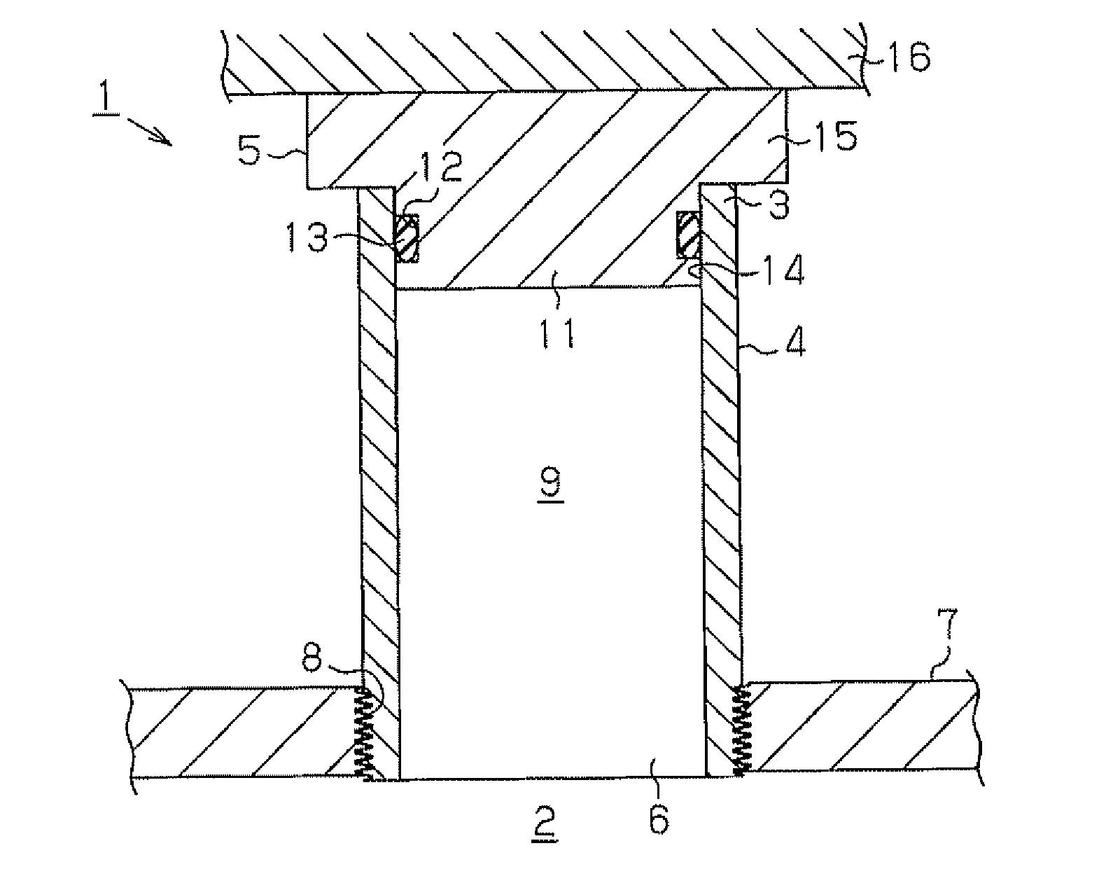
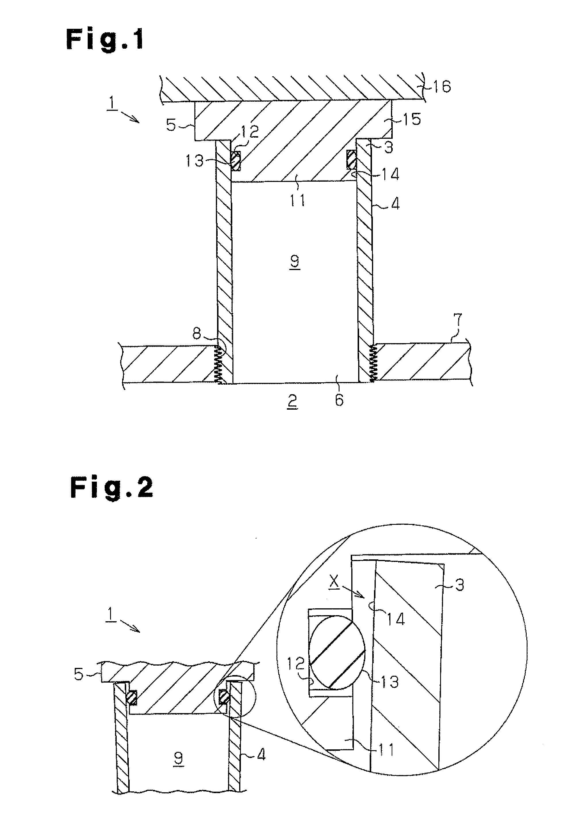
[0029]A safety valve 1 according to the present embodiment shown in FIG. 1 includes a cylinder 4 having a substantially circular cross section and a plug 5. The cylinder 4 has an open end 3, which is closed by the plug 5. The open end 3 is one of the axial ends of the cylinder 4 (the upper end as viewed in FIG. 1). The interior 9 of the cylinder 4 communicates with a high-pressure gas passage 2 defined by a pipe wall 7.

[0030]A connection hole 8 is formed in the pipe wall 7. The cylinder 4 has a connection end 6, which is an axial end of the cylinder 4 (the lower end as viewed in FIG. 1) that is opposite to the open end 3. The cylinder 4 is connected to the pipe wall 7 with the connection end 6 located in the connection hole 8 of the pipe wall 7. The connection end 6 of the cylinder 4 faces the high-pressure gas passage 2. In this embodiment, a thread is formed on the outer circumf...

second embodiment

[0038]A second embodiment of the present invention will now be described with reference to FIGS. 3 to 5.

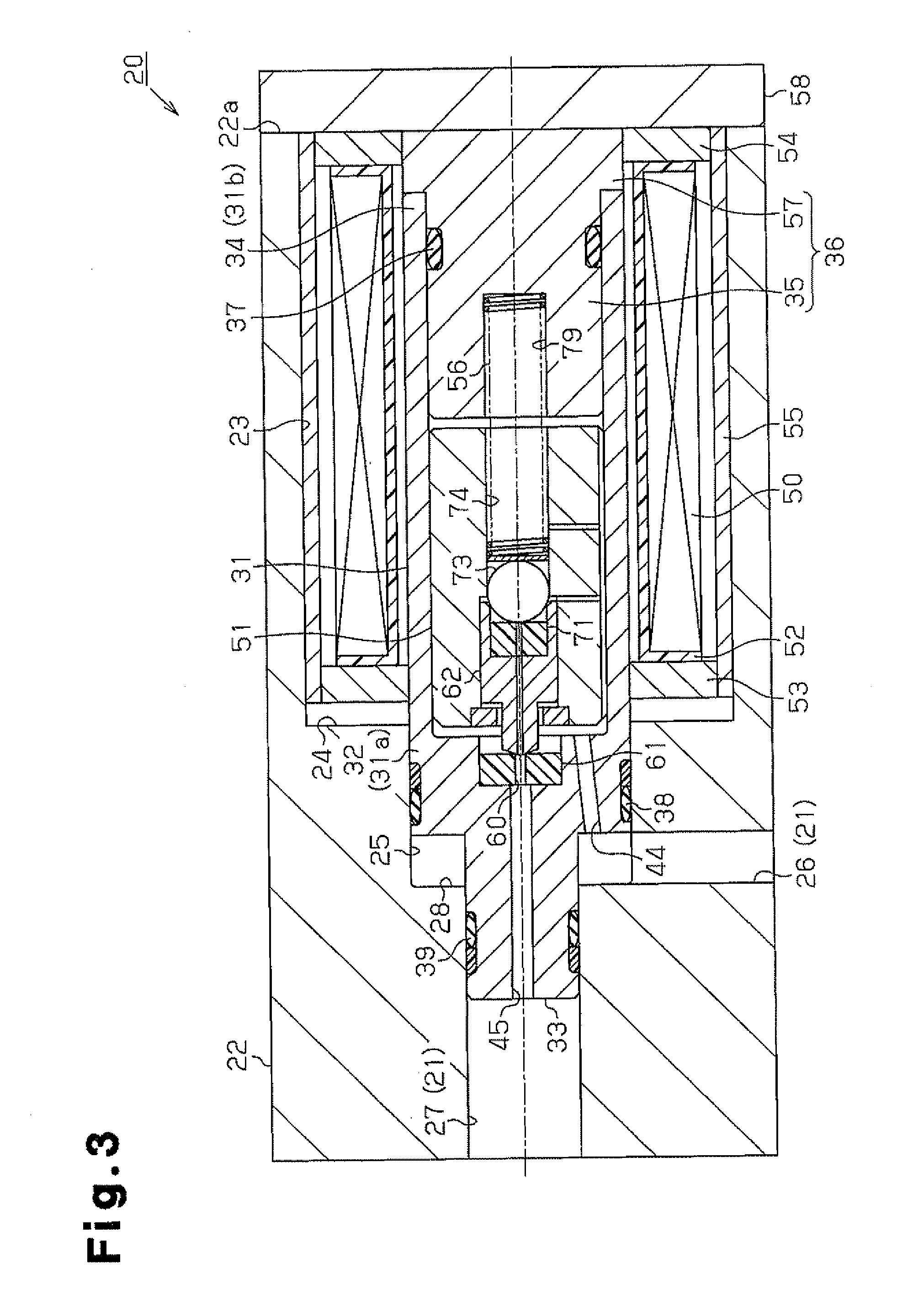
[0039]FIG. 3 shows an electromagnetic valve 20 of the present embodiment. The electromagnetic valve 20 is used in the high-pressure hydrogen gas supply system. The electromagnetic valve 20 is housed in a valve body 22. The valve body 22 is attached to a high-pressure hydrogen gas tank (not shown) to define a part of a high-pressure gas passage 21.

[0040]An accommodation hole 23 having a circular cross section is formed in one end 22a of the valve body 22 (right end as viewed in FIG. 3). An insertion hole 25, the diameter of which is smaller than the accommodation hole 23, is formed in the bottom surface 24 of the accommodation hole 23. The insertion hole 25 is coaxial with the accommodation hole 23. In the present embodiment, the insertion hole 25 also has a circular cross section. The valve body 22 has an inlet port 26, which communicates with the insertion hole 25, and an outlet ...


PUM


Abstract

A safety valve includes a cylinder having an open end and a plug for closing the open end with a hermetic seal. The interior of the cylinder communicates with a high-pressure gas passage. The cylinder is deformed as a function of gas pressure in the high-pressure gas passage to widen the open end. This allows gas in the high-pressure gas passage to escape and thus prevents the gas pressure from increasing beyond an acceptable level.

Description

CROSS-REFERENCE TO RELATED APPLICATION[0001]This application is based on and claims priority from Japanese Patent Application No. 2010-225641 filed on Oct. 5, 2010, the entire contents of which are incorporated herein by reference.BACKGROUND OF THE INVENTION[0002]The present invention relates to a safety valve for preventing gas pressure from increasing beyond an acceptable level and to an electromagnetic valve that serves as the safety valve.[0003]Conventionally, high-pressure gas supply systems such as gas tanks for fuel-cell cars have valve devices. An electromagnetic valve is known as one example of such a valve device and is used for controlling supply of hydrogen gas stored in the gas tank mounted on a fuel-cell car (for example, refer to Japanese Laid-Open Patent Publication No. 2003-240148). Such valve devices function, for example, as safety valves that prevent gas pressure from increasing beyond an acceptable level, that is, such valve devices prevent excessive pressure fr...

Claims


Application Information

Patent Timeline
IPC IPC(8): F16K31/02F16K17/02
CPCF16K17/164F16K31/0686F16K17/02Y02E60/321F16K31/02F16K27/029F16K15/142Y10T137/1624Y10T137/2627Y10T137/2642Y02E60/32
Inventor IMOTO, YOSHINORISUZUKI, HIROAKINUMAZAKI, KAZUSHIUCHIMURA, CHIHIROYAMASHITA, AKIRAISHITOYA, TSUKUOWATANABE, NORITAKA
Owner JTEKT CORP
Why Eureka
Try Eureka