This helps you quickly interpret patents by identifying the three key elements:
Problems solved by technology
Method used
Benefits of technology
Benefits of technology
[0023] The primary objective of the present invention is to provide a method and apparatus for inking a lens that can improve the production efficiency and reduce the cost.
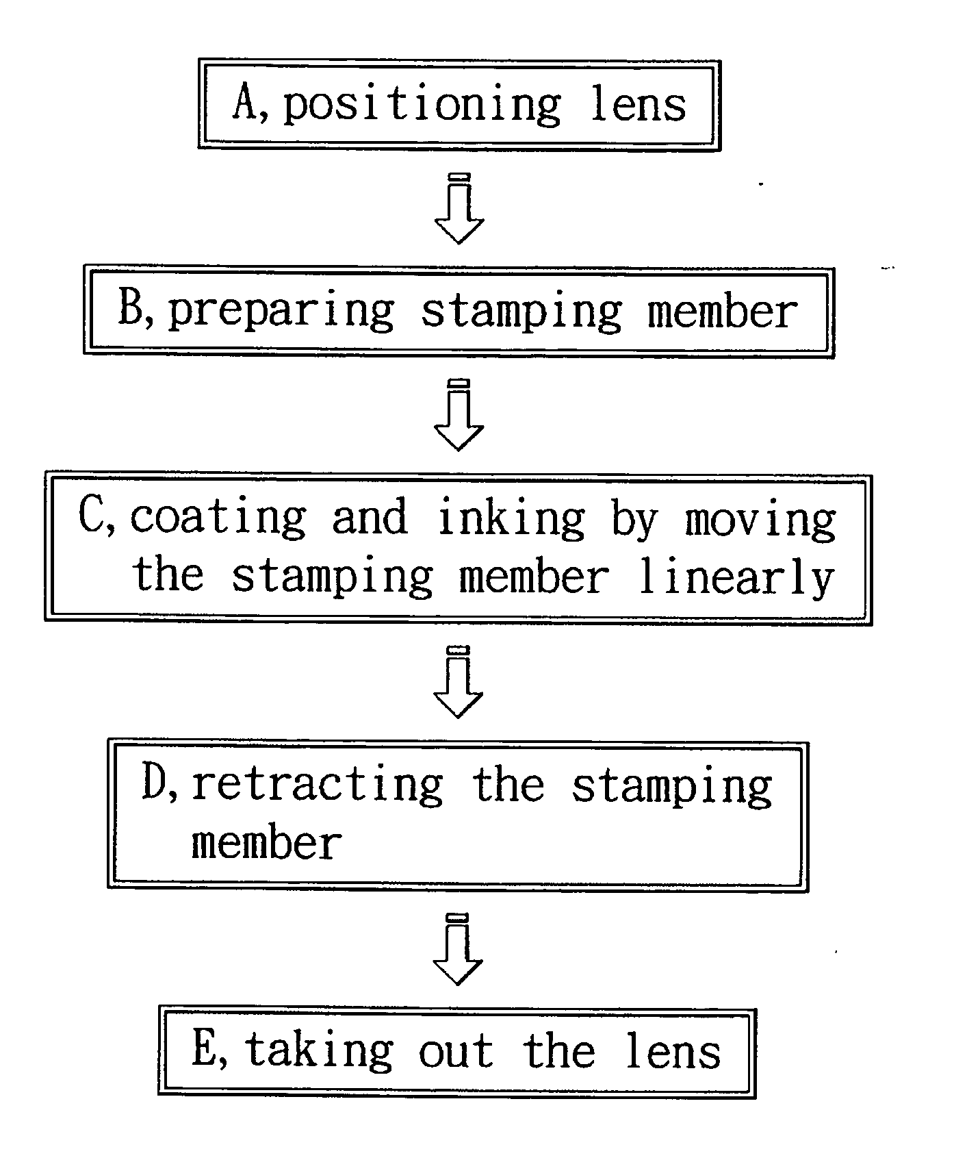
[0024] The present invention operates the steps of: A, positioning lens; B, preparing stamping member; C, coating and inking by moving the stamping member linearly; D, retracting the stamping member; and E, taking out the lens. Utilizing the abovementioned five steps, the present invention can effectively reduce the original manual operation time, it can create a high efficient stamping effect on the basis of quick inking operation. Furthermore, due to the shape, the area, the location and the angle of the inking surface all fit the inactive area of the lens to be inked very well, it can achieve a very good and accurate inked edge.
[0026] The present invention mainly utilizes the step C of coating and inking by moving the stamping member linearly, such technology can enable a plurality of lenses to be inked synchronously. Therefore, it satisfies the requirement of mass production, effectively reducing the cost while improving the production efficiency.
Problems solved by technology
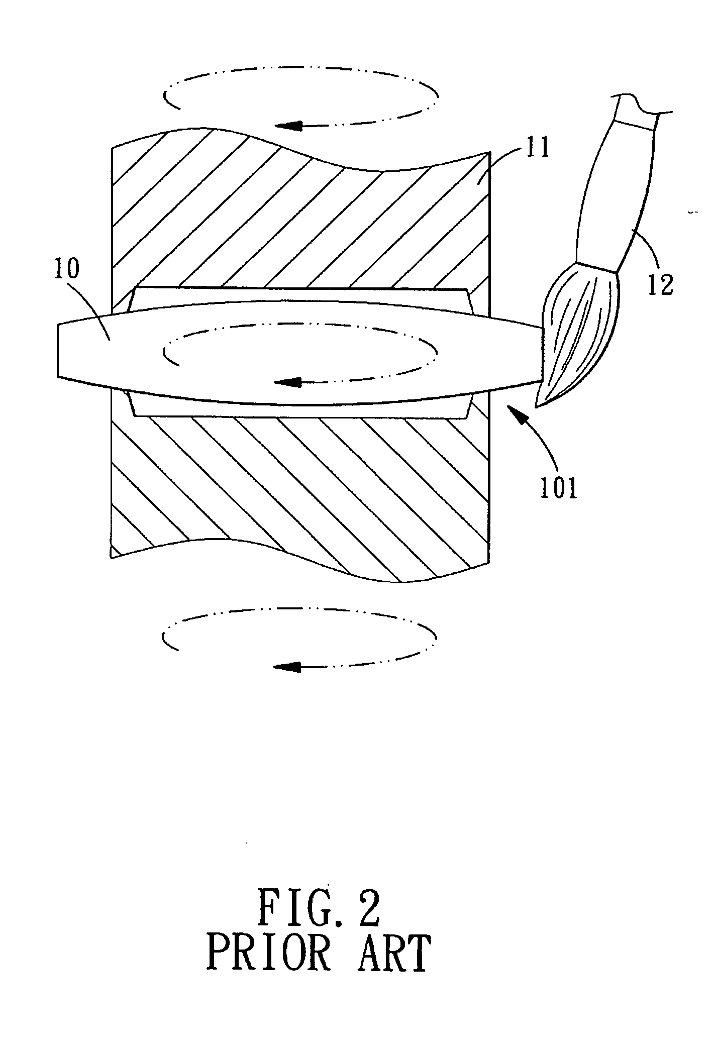
However, nowadays the existing lens are various in shapes (non-axial symmetry inactive area, non-outer periphery inactive area), and have many designs in terms of how they are assembled, not all various lenses can be inked perfectly by the use of positioning device 11.
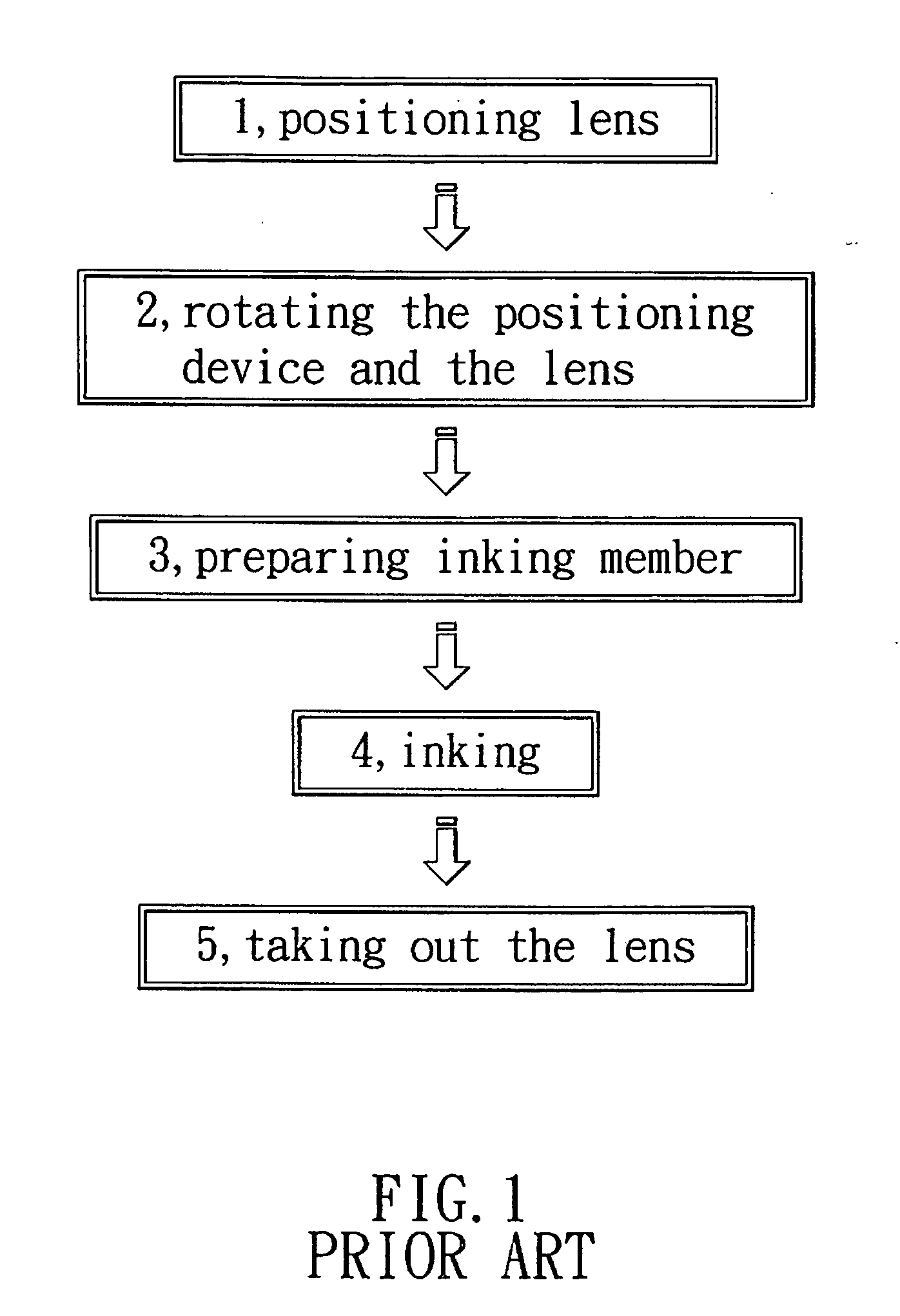
Second, the conventional technology still partially depends on manpower, every piece of lens needs to be rotated and inked respectively, only one piece of lens 10 can be inked at a time, as a result, the inking process is less efficient and unsuitable for mass production.
Third, when applying ink to the inactive area 101 along the periphery of the lens 10, the inking member 12 is unable to coating the ink accurately with the predetermined scope, because the rotation of the positioning device 11 will cause instability of the inking operation, and the inking operation is very likely to cause error.
Method used
Image
Click on the blue label to locate the original text in one second.
Reading with bidirectional positioning of images and text.
Examples
first embodiment
[0041] The lens inking method of the first embodiment is best illustrated by referring to FIGS. 1-6 and comprises the steps of:
[0042] A, positioning lens: positioning the lens 10 in the positioning groove 21 of the positioning member 20, and making the inactive area 101 of the lens 10 protrudes out of the positioning groove 21;
[0043] B, preparing stamping member: forming an inking surface 301 coated with ink 31 on the surface of the stamping member 30;
[0044] C, coating and inking by moving the stamping member linearly: moving the stamping member 30 linearly back and forth with respect to the lens 10 on the positioning member 20, and making the inking surface 301 contact the inactive area 101 of the lens 10, so as to apply the ink 31 of the inking surface 301 fully to the inactive area 101 of the lens 10.
[0045] D, retracting the stamping member: moving the stamping member 30 back to its original position;
[0046] E, taking out the lens: taking the lens 10 out of the positioning gro...
second embodiment
[0047] Referring to FIG. 7, the present invention is illustrated, wherein the inactive area 401 is not located around the periphery of the lens 40. The shape, the area, the location and the angle of the stamping member 50 still fit the inactive area 101 of the lens 10 to be inked, thus the inking operation can be performed without being limited by the variety and the shape of the lens.
[0048] Referring further to FIG. 8, the step C of the present invention is to move a plurality of stamping members 60 linearly back and forth relative to the lenses 10 on the positioning member 70, and between the stamping members 60 and the positioning member 70 a plurality of lenses 10 can be inked synchronously. Therefore, it satisfies the requirement of mass production, effectively reducing the cost while improving the production efficiency.
[0049] As stated above, the present invention uses the following steps and apparatus to coat the lens with ink: A, positioning lens; B, preparing stamping memb...
PUM
Abstract
A method and apparatus for applying ink to the inactive area of a lens, the method comprises the steps of: A, positioning lens; B, preparing stamping member; C, coating and inking by moving the stamping member linearly; D, retracting the stamping member; and E, taking out the lens. The apparatus comprises a stamping member and a positioning member. The stamping member moves linearly back and forth relative to the positioning member, on the surface of the stamping member is formed an inking surface coated with ink. The shape, the area, the location and the angle of the inking surface fit the inactive area of the lens to be inked. The inking surface of the stamping member can contact the inactive area of the lens, so as to enable the inactive area to be fully coated with ink.
Description
BACKGROUND OF THE INVENTION [0001] 1. Field of the Invention [0002] The present invention relates to a method and an apparatus for inking a lens, which includes five steps for coating ink on the inactive area of the optical lens, and uses a stamping member to perform a quick inking operation to the inactive area of the lens. [0003] 2. Description of the Prior Art [0004] The application scope of the modern image taking lens is expanding continuously. However, to comply with the requirement of miniaturizing the solidimage sensor and the image taking lens as well as improving the performance thereof, the apparatus and the technology for lens inking also need to be improved in terms of production efficiency, precision, and assembly complexity. Therefore, along with the popularization of the photographic mobile phone the research and development in terms of inking method and apparatus are becoming more and more urgent. Hence, how to develop a more effective lens inking method has become...
Claims
Application Information
Patent Timeline
Application Date:The date an application was filed.
Publication Date:The date a patent or application was officially published.
First Publication Date:The earliest publication date of a patent with the same application number.
Issue Date:Publication date of the patent grant document.
PCT Entry Date:The Entry date of PCT National Phase.
Estimated Expiry Date:The statutory expiry date of a patent right according to the Patent Law, and it is the longest term of protection that the patent right can achieve without the termination of the patent right due to other reasons(Term extension factor has been taken into account ).
Invalid Date:Actual expiry date is based on effective date or publication date of legal transaction data of invalid patent.

