Back plate splicing structure for large-size backlight modules and liquid crystal display

Inactive Publication Date: 2014-10-30
TCL CHINA STAR OPTOELECTRONICS TECH CO LTD
View PDF2 Cites 3 Cited by
  • Summary
  • Abstract
  • Description
  • Claims
  • Application Information

AI Technical Summary

Benefits of technology

The present invention provides a new back plate splicing structure for large-size backlight modules that overcomes the shortcomings of conventional structures. The new structure is simpler and easier to assemble, and requires less screws, reducing both the cost and assembly time. Additionally, it allows for the back plate to be fixed in two dimensions, making it easier to achieve the desired assembly. Overall, this new structure improves labor efficiency and reduces the amount of work necessary.

Problems solved by technology

However, existing methods for producing the back plate by splicing a number of flat plates via screws has the following disadvantages: 1. with much locking and attachment of screws, it requires much labor to assemble the back plate by hand in the production and assembly process, which results in poor mass production performance and low production capacity; 2, with large number of screw holes, missing locking of some screw holes may happen frequently, resulting in the looseness of the back plate; 3, with the large number of screw holes defined in the back plate, the tolerance of the back plate as a whole such as the pressure resistance of the back plate has been reduced greatly, which affects the quality and the lifetime of the back plate.

Method used


Image

  • Back plate splicing structure for large-size backlight modules and liquid crystal display
  • Back plate splicing structure for large-size backlight modules and liquid crystal display
  • Back plate splicing structure for large-size backlight modules and liquid crystal display

Examples


first embodiment

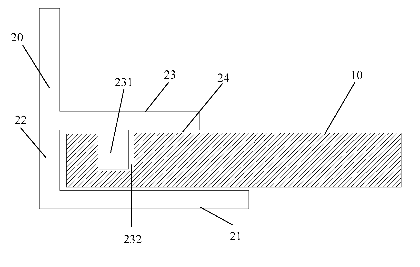
[0033]Referring to FIG. 1, which is schematic view of the back plate splicing structure for large-size backlight modules in accordance with the present disclosure.

[0034]In the back plate splicing structure for large-size backlight modules of the first embodiment, the back plate includes a bottom flat plate 10 and a splicing member 20 joined to an end side of the bottom flat plate 10. The splicing member 20 includes a side plate 22, and an upper supporting plate 23 and a lower supporting plate 21 configured on a same side of the side plate 22 and being perpendicular to the side plate 22. A top surface of the lower supporting plate 21, the side plate 22, and a bottom surface of the upper supporting plate 23 cooperatively define a clamping opening which clamps the bottom flat plate 10 therein. A protruding post 231 is configured on the bottom surface of the upper supporting plate 23, and a groove 232 engageable with the protruding post 231 is defined in the bottom flat plate 10. Additi...

second embodiment

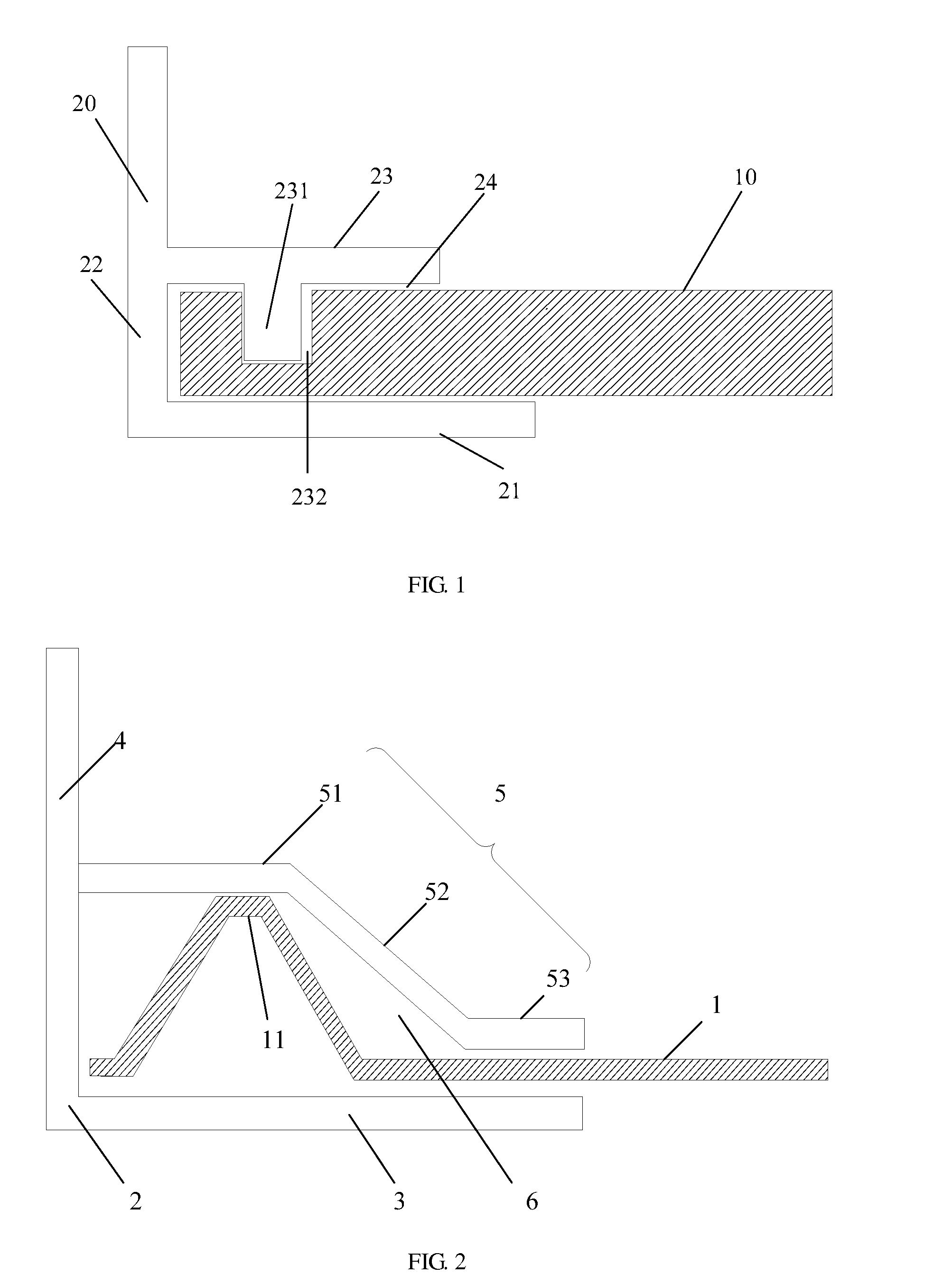
[0039]Referring further to FIG. 2, which is a schematic view of a back plate splicing structure for large-size backlight modules in accordance with the present disclosure.

[0040]In the back plate splicing structure for large-size backlight modules of the second embodiment of the present disclosure, the back plate includes a bottom flat plate 1 and a splicing member 2 joined to an end of the bottom flat plate 1. The splicing member 2 includes a side plate 4, and an upper supporting plate 5 and a lower supporting plate 3 configured on the same side of the side plate 4. The upper supporting plate 5 includes a connecting portion 51 perpendicularly configured on the side plate 4, a clamping surface portion 53 contacting the bottom flat plate, and an inclined surface portion 52 which connects the connecting portion 51 and the clamping surface portion 53. The connecting portion 51, the inclined surface portion 52, the lower supporting plate 1, and the side plate 1 cooperatively define a cla...

third embodiment

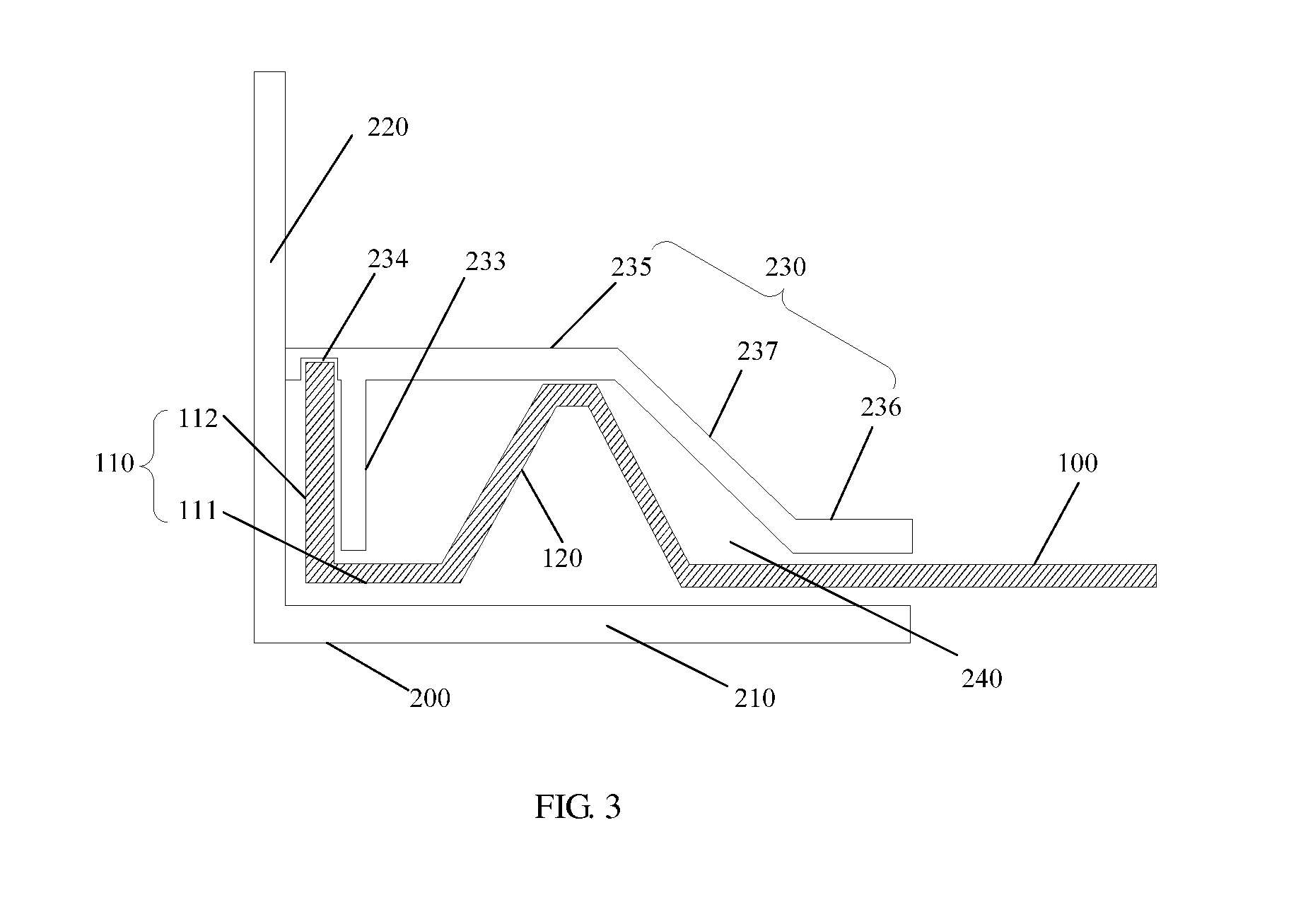
[0043]Referring further to the FIG. 3, which is a schematic view of a back plate splicing structure for large-size backlight modules in accordance with the present disclosure.

[0044]In the third embodiment, the back plate includes a bottom flat plate 100 and a splicing member 200 joined to an end of the bottom flat plate 100. The splicing member 200 includes a side plate 220, and an upper supporting plate 230 and a lower supporting plate 210 configured on a same side of the side plate 220. The upper supporting plate 230, the lower supporting plate 210, and the side plate 220 cooperatively define a clamping opening 240 clamping the bottom flat plate 100 therein. A protrusion 233 is configured on a clamping surface of the upper supporting plate 230, and a curved clamp 110 clamping the protrusion 233 therein is configured on one end of the bottom flat plate 100. At least one fixing screw (not shown in the drawings) is configured between the bottom flat plate 100 and the splicing member ...


PUM


Abstract

The present disclosure provides a back plate splicing structure for large-size backlight modules. The back plate includes a bottom flat plate and a splicing member joined to an end of the bottom flat plate, wherein the splicing member includes a side plate, and an upper supporting plate and a lower supporting plate configured on a same side of the side plate; the upper supporting plate, the lower supporting plate, and the side plate cooperatively define a clamping opening clamping the bottom flat plate therein; the upper supporting plate fixes the bottom flat plate in the clamping opening, and at least one fixing screw is configured between the bottom flat plate and the splicing member.

Description

BACKGROUND[0001]1. Technical Field[0002]The present disclosure relates to liquid crystal displaying technologies, and particularly, to a back plate splicing structure for large-size backlight modules and a liquid crystal display with the same.[0003]2. Description of Related Art[0004]With the innovation of LCD technologies, large-size liquid crystal televisions become more and more mature and simultaneously become cheaper and cheaper. The innovation of the technology of large-size backlight source has become a trend. At present, back plates of most of large-size backlight modules are formed by splicing a number of flat plates.[0005]However, existing methods for producing the back plate by splicing a number of flat plates via screws has the following disadvantages: 1. with much locking and attachment of screws, it requires much labor to assemble the back plate by hand in the production and assembly process, which results in poor mass production performance and low production capacity;...

Claims


Application Information

Patent Timeline
IPC IPC(8): F16B5/00G02F1/1333
CPCG02F1/1333F16B5/0004F16B5/0635G02F1/133308Y10T403/7016G02F1/133317G02F1/133314
Inventor KUO, YI-CHENGHSIAO, YUCHUNZHANG, YANXUE
Owner TCL CHINA STAR OPTOELECTRONICS TECH CO LTD
Why Eureka
Try Eureka