

Compact disc handling apparatus
- Summary
- Abstract
- Description
- Claims
- Application Information
AI Technical Summary
Benefits of technology
Problems solved by technology
Method used
Image

Examples
Embodiment Construction
[0028]The present invention will be clearer from the following description when viewed together with the accompanying drawings, which show, for purpose of illustrations only, the preferred embodiment in accordance with the present invention.
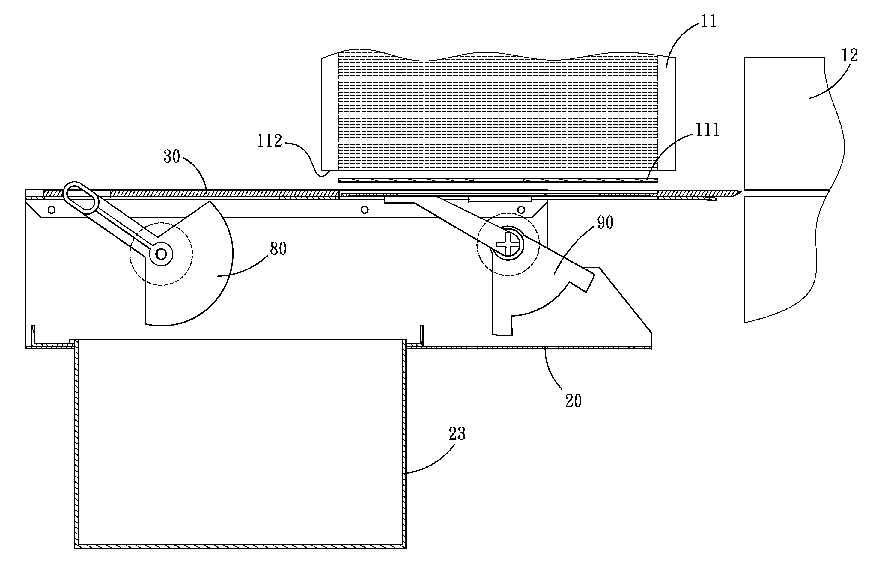
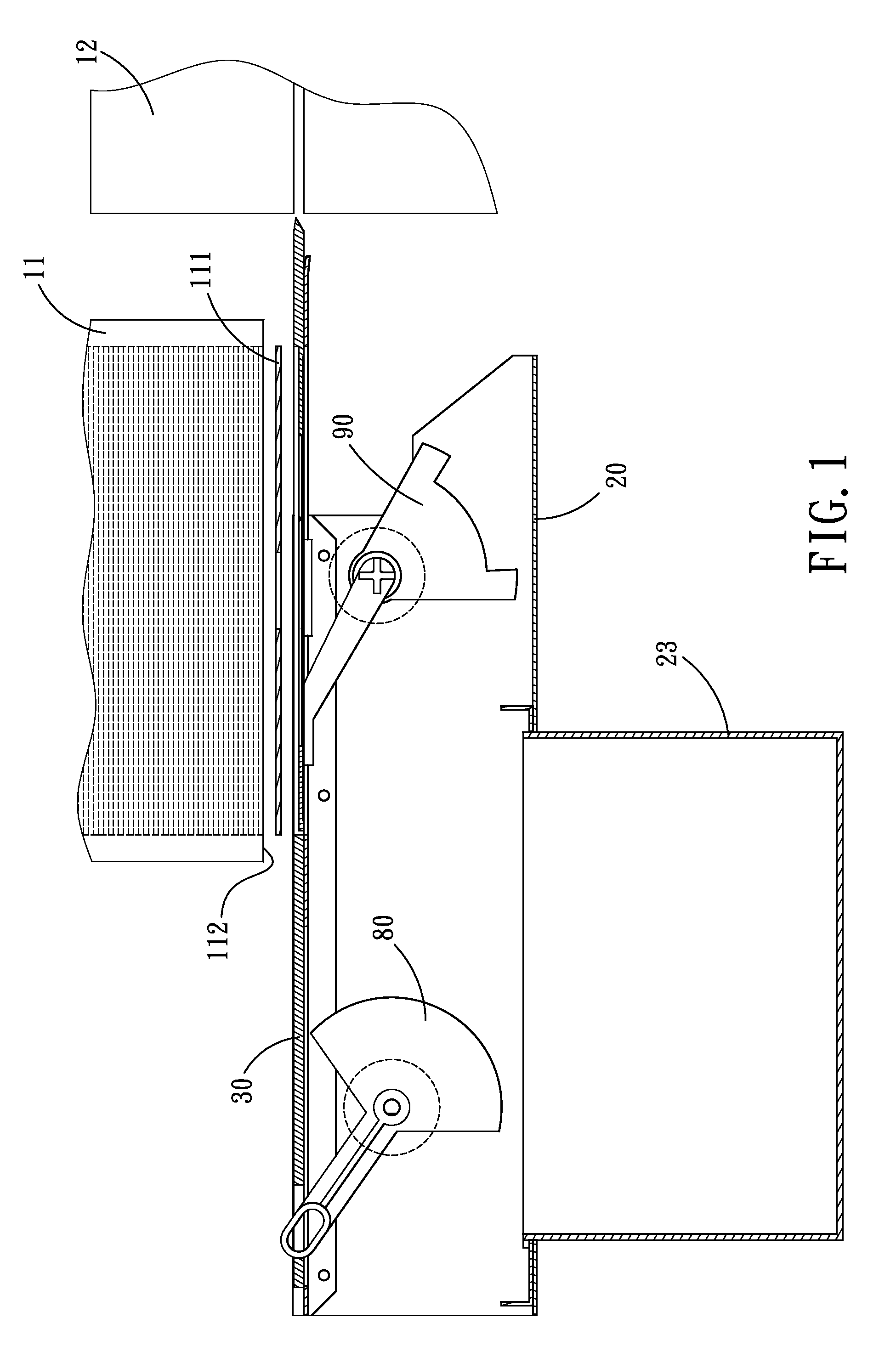
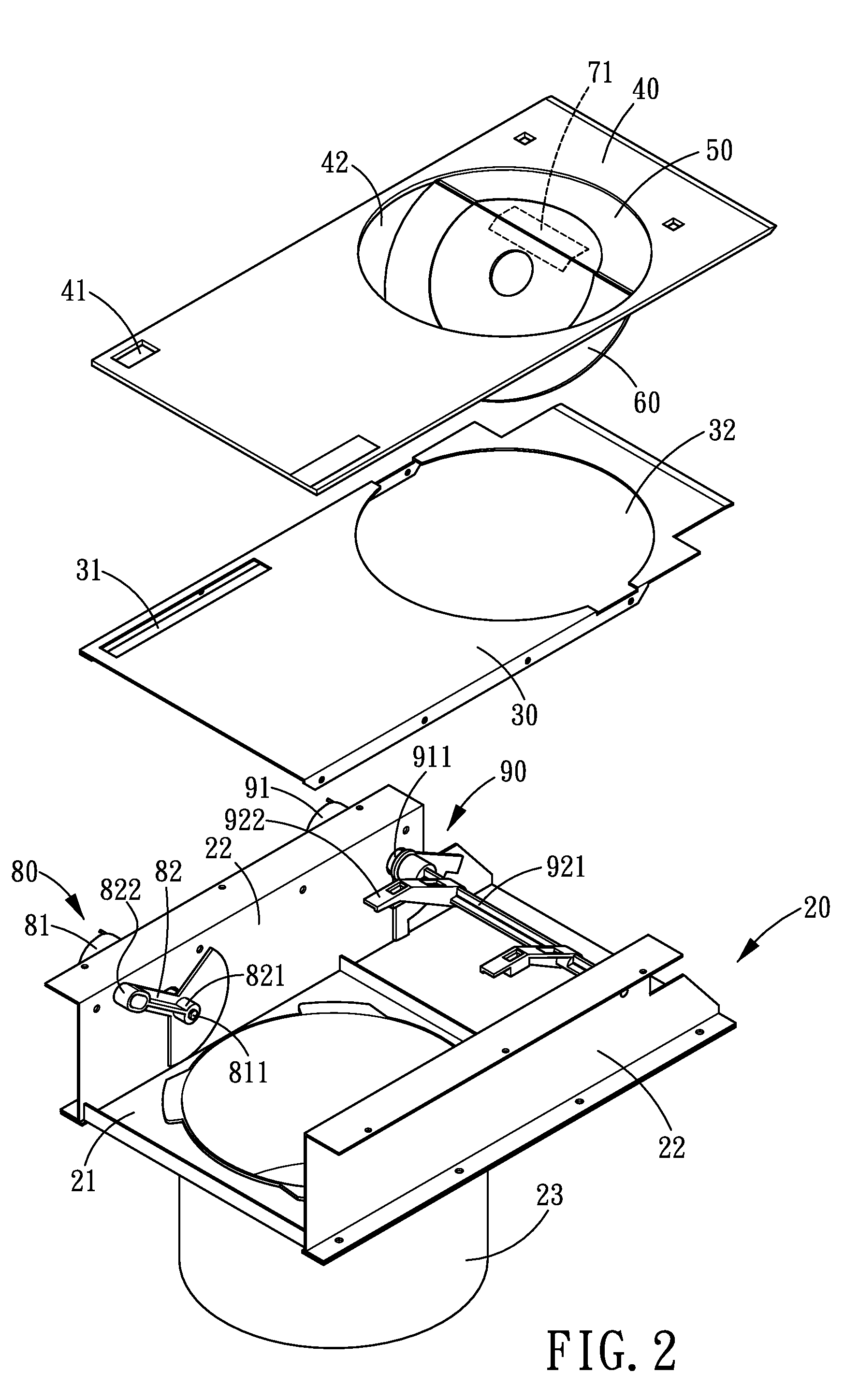
[0029]Referring to FIGS. 1-4A, a compact disc handling apparatus in accordance with a first embodiment of the present invention is provided to carry a compact disc 111 supplied from a disc-supplying apparatus 11 into or out of a printing mechanism 12 for performing a surface printing operation and essentially comprises a frame body 20, a fixed board 30, a sliding board 40, a fixed plate 50, a movable plate 60, a movable unit 70, a drive unit 80 and a control unit 90.
[0030]The frame body 20 includes a bottom board 21 and two side boards 22 that are disposed at both sides of the bottom board 21. The bottom board 21 is assembled with a compact disc collecting vessel 23.
[0031]The fixed board 30 includes an elongated slot 31 and a through hole 32 and ...
PUM
 Abstract
Description
Claims
Application Information