Control device for automatic transmission

a control device and automatic transmission technology, applied in the direction of instruments, vehicle sub-unit features, transportation and packaging, etc., can solve the problems of giving an uncomfortable feeling to the driver of the vehicle, common problems such as the above, and achieve the effect of reducing the load on the electric pump assisting the mechanical pump, reducing the heat generation of the electric pump, and increasing the oil pressure generated by the mechanical pump

Inactive Publication Date: 2012-04-05
AISIN AW CO LTD
View PDF0 Cites 15 Cited by
  • Summary
  • Abstract
  • Description
  • Claims
  • Application Information

AI Technical Summary

Benefits of technology

[0035]According to the control device for the automatic transmission having the foregoing structure, since a so-called downshift is performed when the heat generation condition regarding the electric pump is met, the rotation speed of the input shaft can be increased to increa...

Problems solved by technology

Therefore, there is a possibility of giving an uncomfortable feeling to the driver of the vehicle.
Incidentally, the foregoing pro...

Method used


Image

  • Control device for automatic transmission
  • Control device for automatic transmission
  • Control device for automatic transmission

Examples


first embodiment

A. First Embodiment

A1. Structure of Vehicle

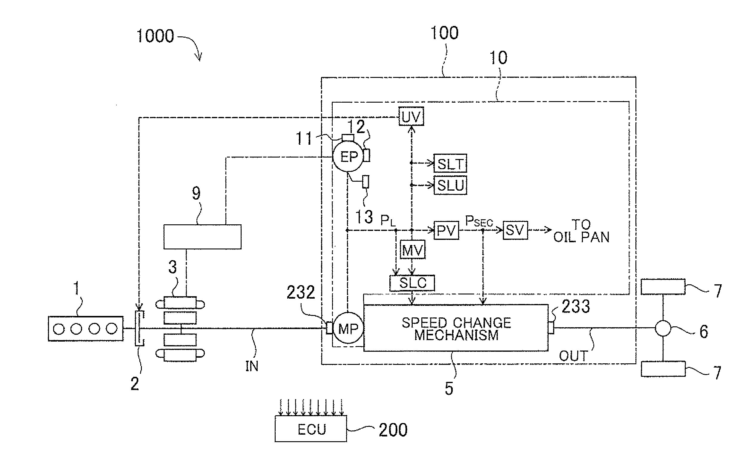
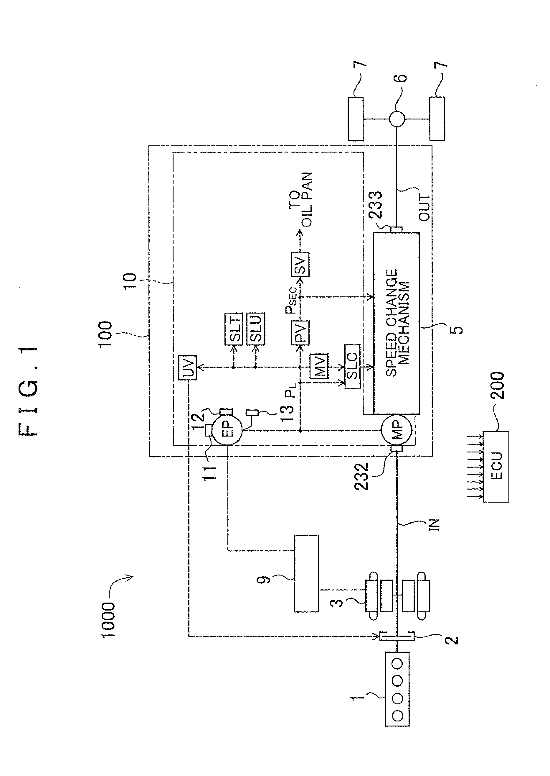
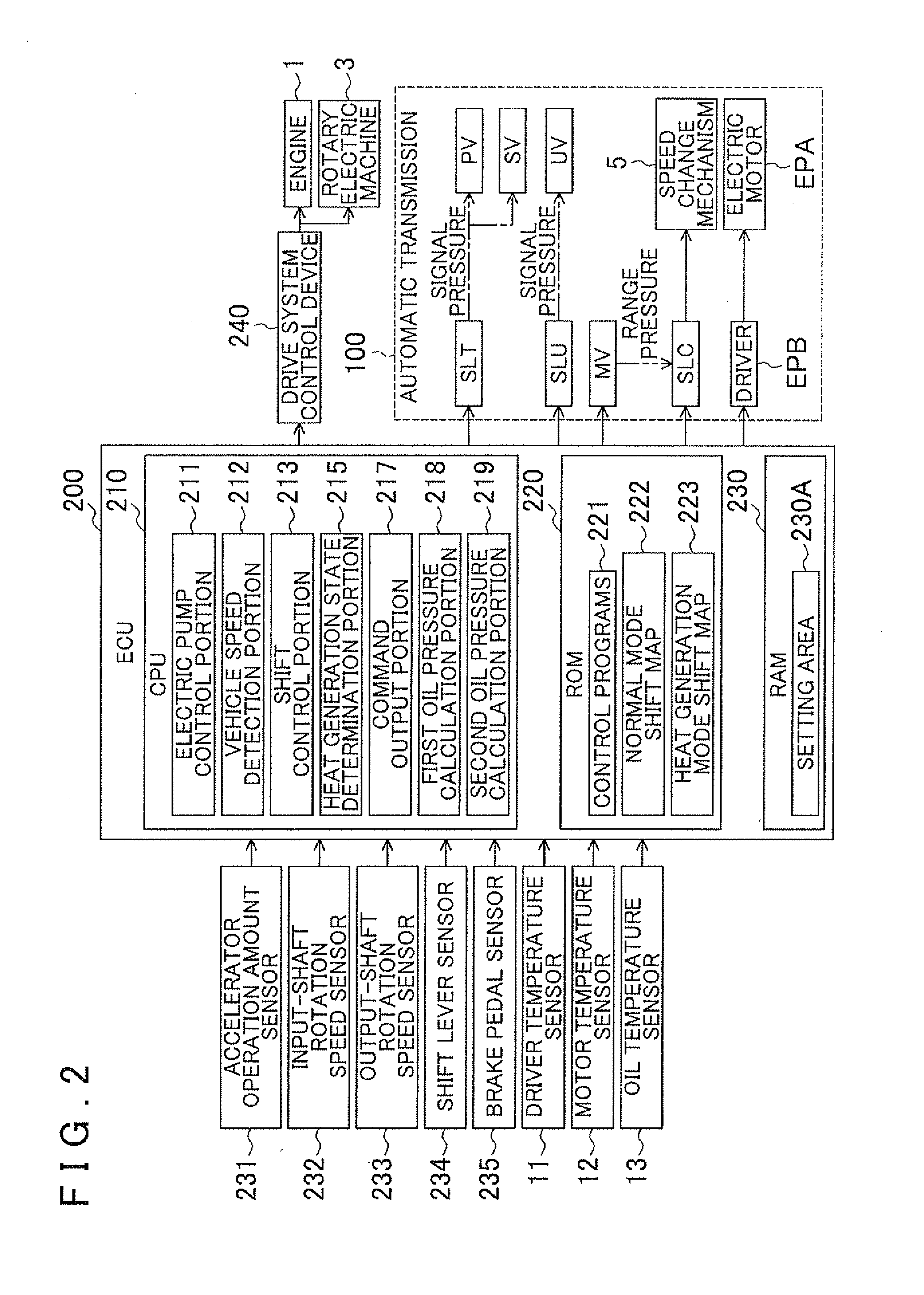
[0048]FIG. 1 is a diagram schematically showing a structure of a vehicle 1000 as an embodiment of the present invention. In FIG. 1, structures related to the vehicle 1000 are selectively shown in order to avoid complications of the drawing. Incidentally, in FIG. 1, solid lines show transfer paths of drive force, and interrupted lines show supply paths of an operating oil ATF (Automatic Transmission Fluid), and a one-dot chain line shows electrical connection. FIG. 2 is a diagram showing functional blocks of an electronic control unit 200 (also termed the ECU (Electric Control Unit)).

[0049]The vehicle 1000 of this embodiment is a hybrid vehicle that uses an engine and a motor as drive force sources. This vehicle 1000, as shown in FIG. 1 or FIG. 2, is furnished with an engine 1, a transfer clutch 2, a rotary electric machine 3, a differential device 6, wheels 7, an electricity storage device 9, an input shaft IN, an output shaft OUT, an autom...

second embodiment

B. Second Embodiment

[0116]FIG. 8 is a diagram schematically showing a structure of a vehicle 1000A of a second embodiment. The vehicle 1000A of the second embodiment differs in structure from the vehicle 1000 of the first embodiment in having a transfer clutch 300. In the vehicle 1000A, the structures excluding the transfer clutch 300 are substantially the same as those of the first embodiment. In the vehicle 1000A, the same structures as those of the vehicle 1000 of the first embodiment are denoted by the same reference characters as used for the vehicle 1000, and the description thereof will be omitted.

[0117]In the vehicle 1000A, the transfer clutch 300 is disposed on an input shaft IN between a rotary electric machine 3 and a mechanical pump MP. The transfer clutch 300 is supplied with oil pressure transferred from a transfer clutch control valve (not shown) of an oil pressure control device 10, and is thereby controlled to an engaged state or a released state. The transfer clutc...

third embodiment

C. Third Embodiment

[0120]FIG. 9 is a diagram schematically showing a structure of a vehicle 1000B of a third embodiment. The vehicle 1000B of the third embodiment differs in structure from the vehicle 1000 of the first embodiment in having a torque converter 400. In the vehicle 1000B, the structures excluding the torque converter 400 are substantially the same as those of the vehicle 1000 of the first embodiment. In the vehicle 1000B, the same structures as those of the vehicle 1000 of the first embodiment are denoted by the same reference characters as used for the vehicle 1000, and the description thereof will be omitted.

[0121]In the vehicle 1000B, an input shaft IN is formed of an input shaft IN 1 and an input shaft IN2. The input shaft IN1 is linked to a rotary electric machine 3, and the input shaft IN2 is linked to a speed change mechanism 5.

[0122]The torque converter 400 is furnished with a pump impeller 42, a turbine runner 43, a stator 44, a one-way clutch 45, and a lockup ...


PUM


Abstract

A control device for an automatic transmission configured with a command output portion that outputs a command that causes an electric pump to be driven so that oil pressure generated by the mechanical pump and the electric pump becomes greater than or equal to a needed oil pressure for a speed change mechanism when the oil pressure generated by the mechanical pump is smaller than the needed oil pressure. A determination portion determines whether or not a predetermined heat generation condition is met when the command is output by the command output portion. A shift control portion that, in a case where the determination portion has determined that the heat generation condition is met, performs a shift control of causing the speed ratio of the speed change mechanism to become higher than the speed ratio occurring when the determination portion determines that the heat generation condition is met.

Description

INCORPORATION BY REFERENCE[0001]The disclosure of Japanese Patent Application No. 2010-220824 filed on Sep. 30, 2010 including the specification, drawings and abstract is incorporated herein by reference in its entirety.BACKGROUND OF THE INVENTION[0002]The present invention relates to a control device for an automatic transmission and, more particularly, to a control device for an automatic transmission that has an electric pump and a mechanical pump.DESCRIPTION OF THE RELATED ART[0003]There is known a vehicle equipped with an automatic transmission that is furnished with pumps for generating oil pressure for performing control of a speed change mechanism which are a mechanical pump that is driven by rotation drive force provided by a drive force source, and an electric pump that is driven independently of the mechanical pump (e.g., refer to Japanese Patent Application Publication No. JP-A-2009-74592). As such a vehicle, for example, a hybrid vehicle furnished with an engine and a m...

Claims


Application Information

Patent Timeline
IPC IPC(8): F16H61/30
CPCB60Y2400/302F16H61/0213B60Y2300/1865F16H2061/0241F16H61/0031B60Y2300/67B60W20/30B60W2510/107
Inventor TAJIMA, YOICHIHAKUMURA, YOMEI
Owner AISIN AW CO LTD
Why Eureka
Try Eureka