Substrate with shaped cooling holes and methods of manufacture

a cooling hole and substrat technology, applied in the field of turbines, can solve the problem that the cooling arrangement of effusion is not suitable for combustor liners, and achieve the effect of improving film effectiveness

Inactive Publication Date: 2012-05-03
GENERAL ELECTRIC CO
View PDF10 Cites 45 Cited by
  • Summary
  • Abstract
  • Description
  • Claims
  • Application Information

AI Technical Summary

Benefits of technology

[0016]Embodiments of a shaped cooling hole for use in effusion cooling components, such as combustor liners of gas turbines, with improved film effectiveness at little loss of bore convective cooling, together with methods for making the same, as herein shown, described and claimed. Various features and advantages of embodiments of the shaped cooling hole will become apparent by reference to the following description taken in connection with the accompanying drawings.

Problems solved by technology

However, this type of effusion cooling arrangement tends to be unsuitable for combustor liners because such three-dimensional downstream diffusion removes a significant amount of thermal barrier coating (“TBC”) from the combustor liner, a disadvantage in combustors where radiation is a substantial part of the heat load.

Method used


Image

  • Substrate with shaped cooling holes and methods of manufacture
  • Substrate with shaped cooling holes and methods of manufacture
  • Substrate with shaped cooling holes and methods of manufacture

Examples


Embodiment Construction

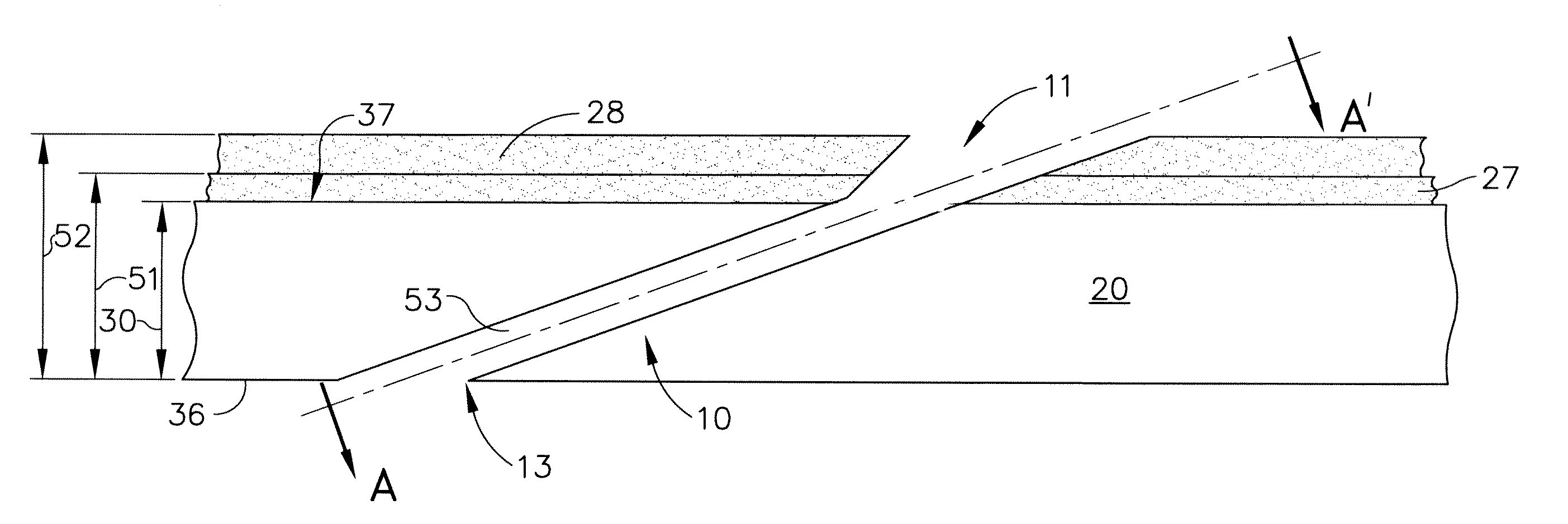
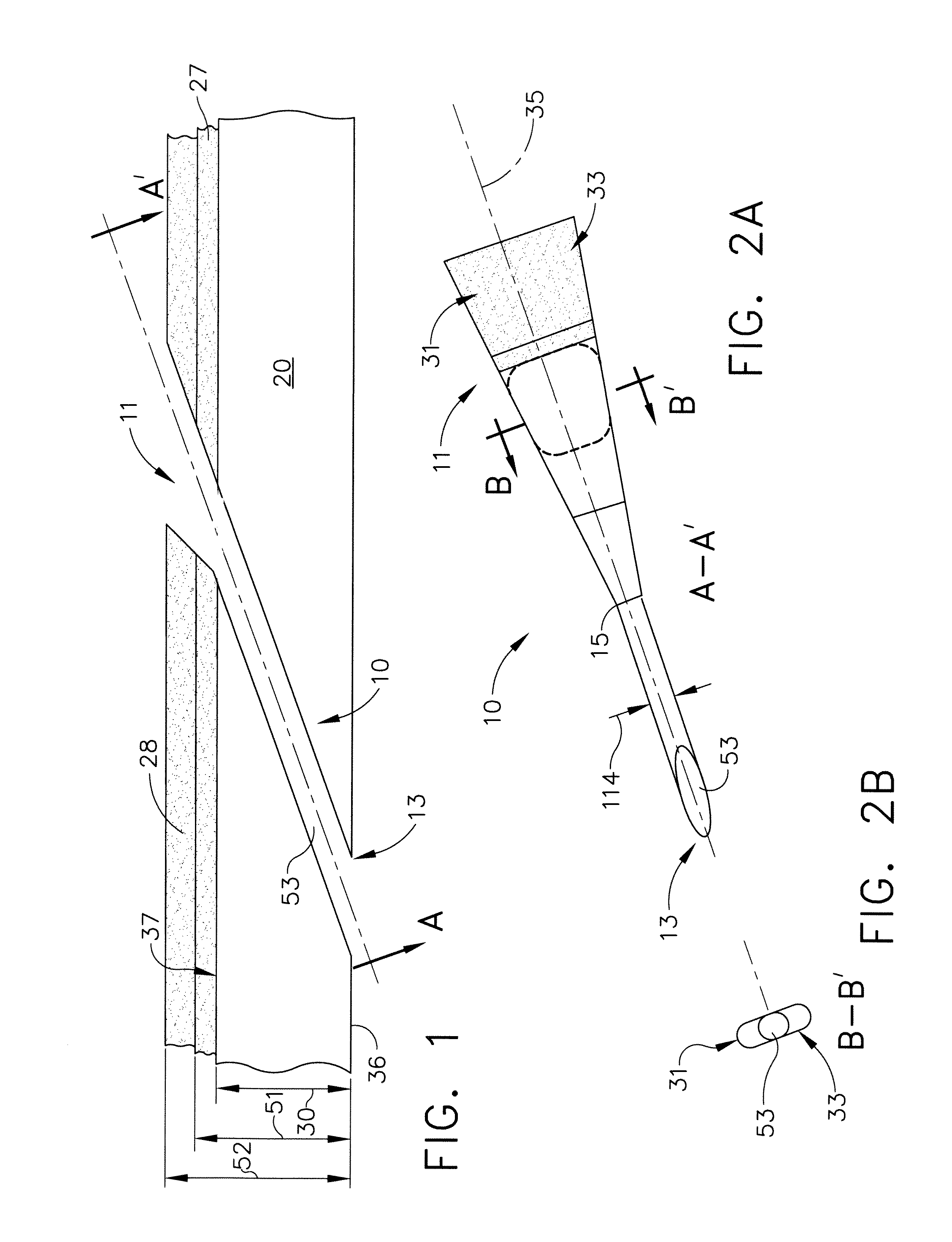
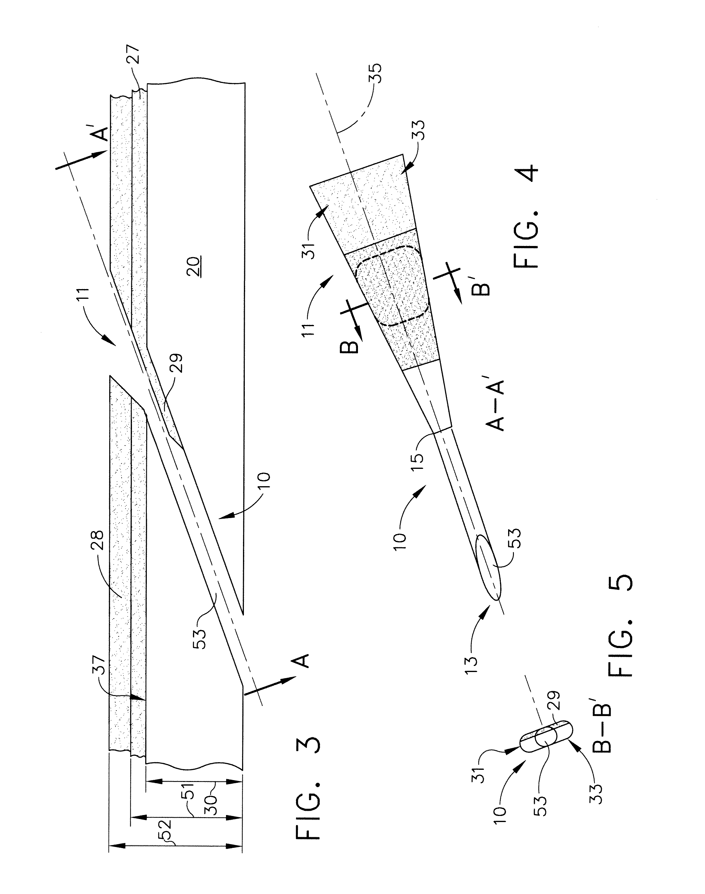
[0045]FIG. 1 is a sectional side view of a substrate 20 coated with one or more layers 27 and / or 28, and having an embodiment of the shaped cooling hole 10 formed at a predetermined angle therein as created by a process of coat and then drill. By way of example, and not limitation, a predetermined angle of the bore 53 relative to an exit surface 37 of the substrate 20 may range from about 20 degrees to 30 degrees. FIG. 2A is another sectional view of the shaped cooling hole of FIG. 1, taken along the line A-A′. FIG. 2B is another sectional view of the shaped cooling hole of FIG. 1, taken along the line B-B′. FIG. 3 is a sectional side view of a substrate coated with a thermal barrier coating and having an embodiment of the shaped cooling hole of FIGS. 1 and 2 formed therein as created by a process of drill then coat and clean. FIG. 4 is another sectional view of the shaped cooling hole of FIG. 3, taken along the line A-A′. FIG. 5 is another sectional view of the shaped cooling hole ...


PUM

PropertyMeasurementUnit
angleaaaaaaaaaa
backside temperaturesaaaaaaaaaa
transition pointaaaaaaaaaa

Abstract

A substrate having one or more shaped effusion cooling holes formed therein. Each shaped cooling hole has a bore angled relative to an exit surface of the combustor liner. One end of the bore is an inlet formed in an inlet surface of the combustor liner. The other end of the bore is an outlet formed in the exit surface of the combustor liner. The outlet has a shaped portion that expands in only one dimension. Also methods for making the shaped cooling holes.

Description

CROSS-REFERENCE TO RELATED APPLICATIONS[0001]Not ApplicableSTATEMENT REGARDING FEDERALLY SPONSORED RESEARCH OR DEVELOPMENT[0002]Not ApplicableNAMES OF PARTIES TO A JOINT RESEARCH AGREEMENT[0003]Not ApplicableREFERENCE TO A SEQUENCE LISTING, A TABLE, OR COMPUTER PROGRAM LISTING APPENDIX SUBMITTED ON COMPACT DISC[0004]Not ApplicableBACKGROUND OF THE INVENTION[0005]1. Field of the Invention[0006]The field of the invention relates to turbines generally, and more particularly to certain new and useful advances in the manufacture and / or cooling of gas turbine combustor liners, of which the following is a specification, reference being had to the drawings accompanying and forming a part of the same.[0007]2. Description of Related Art[0008]A combustor of a gas turbine is a component or area thereof in which combustion of fuel occurs, and which affects various engine characteristics, including emissions and / or fuel efficiency. The purpose of combustors is to regulate the combustion of fuel a...

Claims


Application Information

Patent Timeline
Patent Type & Authority Applications(United States)
IPC IPC(8): F23R3/42B23K26/00B32B3/10
CPCB23K26/063B23K26/388F23R3/04Y10T428/24273F23R2900/03041Y02T50/675F23M5/08F23R2900/00018B23K26/0622B23K26/389Y02T50/60
Inventor STARKWEATHER, JOHN HOWARD
Owner GENERAL ELECTRIC CO
Why Eureka
Try Eureka