Refrigerant compressor

a compressor and refrigerant technology, applied in the direction of positive displacement liquid engines, piston pumps, liquid fuel engines, etc., can solve the problems of many unsolved technical problems, reduce the performance of heat exchangers, and increase the amount of stored oil inside sealed vessels, so as to suppress heat exchanger performance and reduce reliability. , the effect of reducing the amount of stored oil inside the sealed vessel

Inactive Publication Date: 2012-05-03
MITSUBISHI ELECTRIC CORP
View PDF4 Cites 13 Cited by
  • Summary
  • Abstract
  • Description
  • Claims
  • Application Information

AI Technical Summary

Benefits of technology

[0015]The effects of the refrigerant compressor according to the present invention are that discharge rate of oil that is removed from the compressor to the refrigerant circuit can be reduced, thereby enabling deterioration in heat exchanger performance to be suppressed, and that deterioration in reliability due to lubrication failure due to the amount of stored oil inside the sealed vessel being reduced can be suppressed.

Problems solved by technology

Conventionally, some problems have been that if the discharge rate of the oil that is removed to the refrigerant circuit increases, heat exchanger performance is reduced, and in addition if the amount of oil stored inside the sealed vessel is reduced, deterioration in reliability may arise due to lubrication failure.
At the same time, since oil separating mechanisms inside the sealed vessel are complicated, and observational experiments also cannot be performed easily, there are many unexplained portions, and there are also many unsolved technical problems.

Method used


Image

  • Refrigerant compressor
  • Refrigerant compressor
  • Refrigerant compressor

Examples


embodiment 1

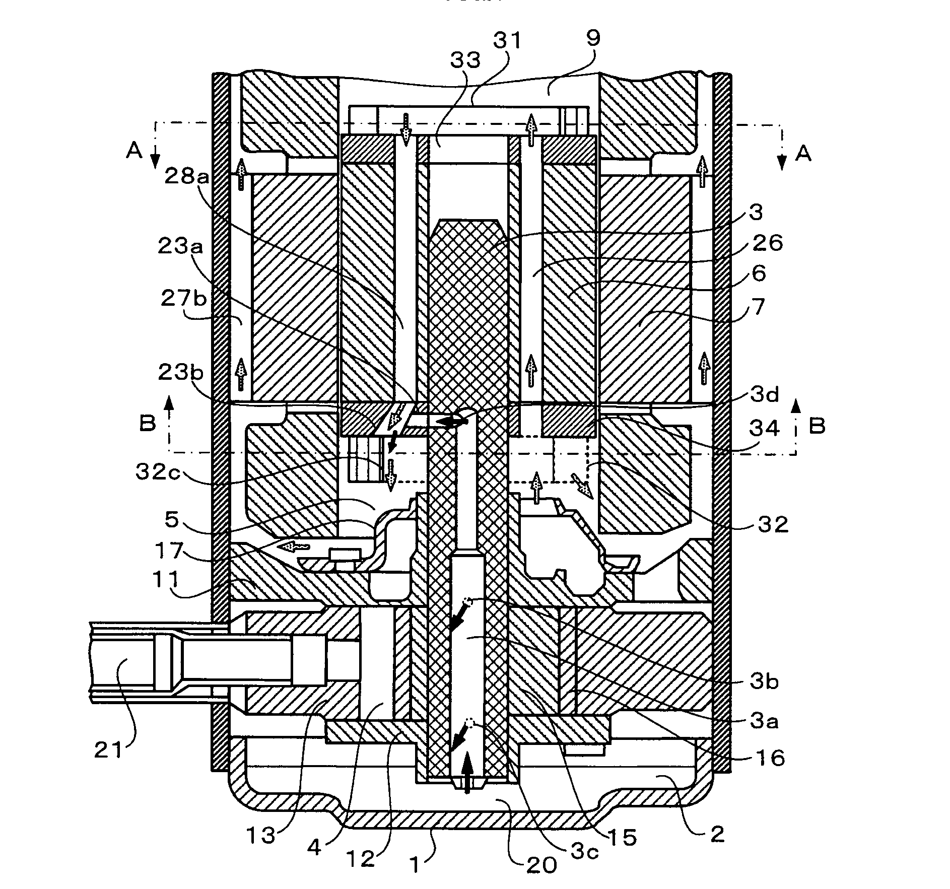
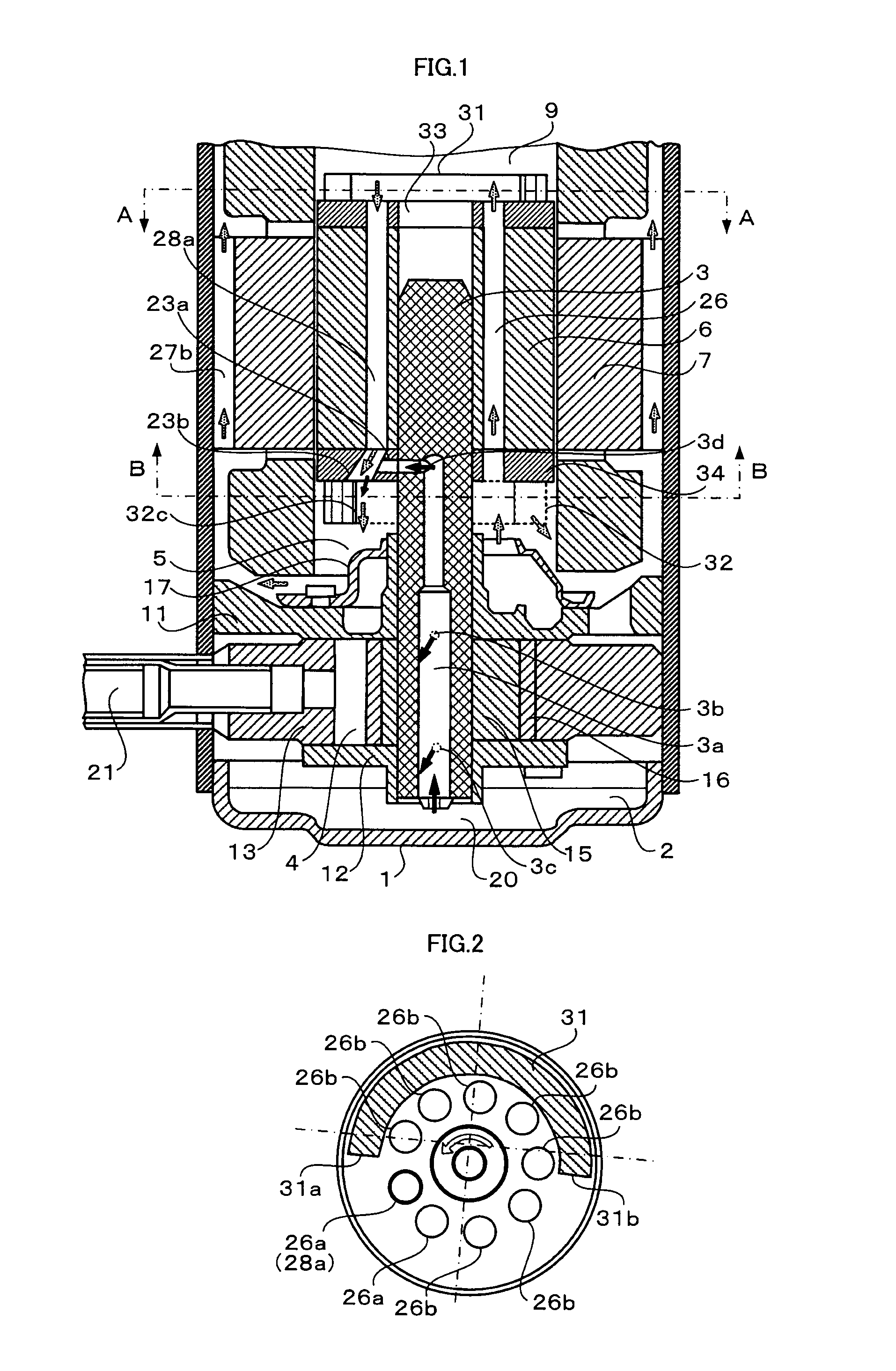
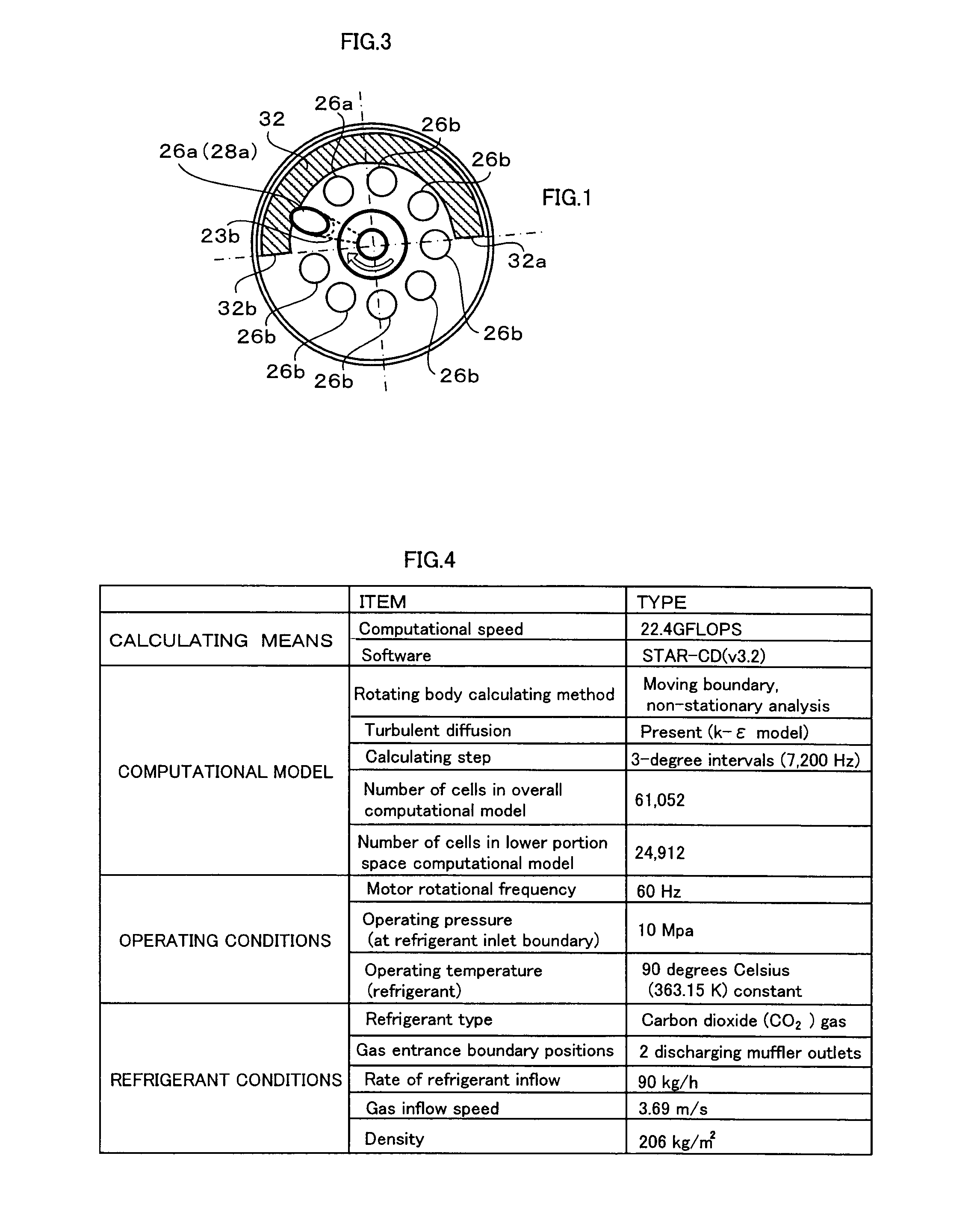
[0028]FIG. 1 is a longitudinal cross section that shows a construction of a rotary compressor according to Embodiment 1 of the present invention. FIG. 2 is a schematic layout of lateral cross section A in FIG. 1. FIG. 3 is a schematic layout of lateral cross section B in FIG. 1.

[0029]First, basic construction and operation of a rotary compressor that functions as a refrigerant compressor according to Embodiment 1 of the present invention will be explained. Moreover, in FIG. 1, solid black arrows indicate oil flow, and stippled arrows indicate refrigerant gas flow.

[0030]As shown in FIG. 1, a rotary compressor according to Embodiment 1 of the present invention includes: an electric motor that has a stator 7 and a rotor 6; and a compressing mechanism to which torque from the electric motor is transmitted by the crank shaft 3, and in which refrigerant gas is compressed inside a cylinder chamber 4.

[0031]The compressing mechanism includes: an upper bearing member 11; a lower bearing membe...

embodiment 2

[0054]FIG. 7 is a longitudinal cross section that shows a construction of a rotary compressor according to Embodiment 2 of the present invention. FIG. 8 is a schematic layout of lateral cross section A in FIG. 7. FIG. 9 is a schematic layout of lateral cross section B in FIG. 7.

[0055]In a rotary compressor according to Embodiment 2 of the present invention, an oil separating plate 35 is added to the rotary compressor according to Embodiment 1 of the present invention, and a rotor 6B, an upper counterweight 31B, a lower counterweight 32B, a rotor upper portion fixed plate 33B, and a rotor lower portion fixed plate 34B are different, and because other portions are similar, identical numbering will be given to similar portions and explanation thereof will be omitted.

[0056]A ring-shaped oil separating plate 35 is fitted over an upper end portion of the crank shaft 3 so as to be tightly fitted, and is held so as to be separated from the upper ends of the rotor vents 26 of the upper count...

embodiment 3

[0069]FIG. 10 is a longitudinal cross section that shows a construction of a scroll compressor according to Embodiment 3 of the present invention. FIG. 11 is a schematic layout of lateral cross section A in FIG. 10. FIG. 12 is a perspective that shows a rotor upper portion of the scroll compressor according to Embodiment 3 of the present invention.

[0070]A scroll compressor according to Embodiment 3 of the present invention includes a scroll compressing mechanism and an electric motor, and because the scroll compressor is conventional, configuration thereof will be explained simply. The electric motor differs in that oil return flow channels have been added, and because other portions thereof are conventional, configuration thereof will be explained simply.

[0071]The scroll compressing mechanism includes: a fixed scroll 51; a crank shaft 3 that is supported rotatably by a main bearing 54 and an auxiliary bearing 55; and an orbiting scroll 52 that is fitted over and driven by a first e...


PUM


Abstract

A refrigerant compressor includes: an electric motor including a stator and rotor inside a sealed vessel; a compressing mechanism driven by a crank shaft in the rotor; a lower portion oil pool storing in the sealed vessel lubricating oil that lubricates the compressing mechanism; an upper counterweight on an upper end of the rotor. Refrigerant gas compressed by the compressing mechanism is discharged inside the sealed vessel, passes through a gas channel formed on the electric motor, moves from a lower space to an upper space with respect to the electric motor, and is discharged outside the sealed vessel. An oil return flow channel is formed on the upper end of the rotor toward a lower end from a vicinity of a leading end portion of the upper counterweight in a direction of rotation, and oil expressed in a vicinity of the rotor is directed to the oil return flow channel.

Description

TECHNICAL FIELD[0001]The present invention relates to improvements to a construction that is highly effective in oil separation for electric motor-driven refrigerant compressors that are used in heat pump equipment and refrigerating cycle equipment.BACKGROUND ART[0002]Conventionally, in electric motor-driven refrigerant compressors that are used in heat pump equipment and refrigerating cycle equipment, torque from an electric motor is transmitted to a compressing mechanism by a crank shaft to compress a refrigerant gas using the compressing mechanism. The refrigerant gas is compressed by the compressing mechanism discharges into a sealed vessel, and moves from a lower space to an upper space relative to the electric motor through electric motor portion gas channels, and subsequently discharges to a refrigerant circuit outside the sealed vessel, but lubricating oil that is supplied to the compressing mechanism mixes with the refrigerant gas, and is discharged outside the sealed vesse...

Claims


Application Information

Patent Timeline
Patent Type & Authority Applications(United States)
IPC IPC(8): F04B37/00F04B35/04F04B39/06
CPCF04B39/16F04C18/0215F04C18/356F04C23/008F04C23/02F04C29/023F04C29/028F04C29/045F04C2240/807
Inventor YOKOYAMA, TETSUHIDEKODA, TOSHIHIDENISHIKI, TERUHIKOMAEYAMA, HIDEAKIKATO, TAROSHINGU, KEISUKEHIRAHARA, TAKUHOSEKIYA, SHIN
Owner MITSUBISHI ELECTRIC CORP
Why Eureka
Try Eureka