Gas turbine system

a technology of gas turbines and turbine blades, applied in the direction of hot gas positive displacement engine plants, machines/engines, engine fuctions, etc., can solve the problems of increasing the amount, deteriorating reliability, and becoming more noticeable, so as to increase the amount of water droplets, improve reliability, and increase the amount of inlet fogging

Active Publication Date: 2008-05-06
MITSUBISHI POWER LTD
View PDF9 Cites 12 Cited by
  • Summary
  • Abstract
  • Description
  • Claims
  • Application Information

AI Technical Summary

Benefits of technology

[0005]However, adding a large amount of atomized water upstream of the compressor increases the amount of water droplets adhering on wall surfaces of an inlet duct and a casing. Water films thus formed on the wall surfaces are torn off by a main stream into large water droplets, which are drifted with the main stream and strike against the wall surfaces. That phenomenon may deteriorate reliability with a risk of causing erosion, for example. In particular, it has recently been discussed to increase the amount of inlet fogging. More specifically, while a rate of the amount of inlet fogging with respect to the amount of inlet air was about 1% in the past, the rate has been increased to 3% or more with intent to increase the gas turbine output. However, such an increase in the amount of inlet fogging further increases the amount of water droplets adhering on the wall surfaces, and makes the above-mentioned problem more noticeable.
[0006]Accordingly, it is an object of the present invention to provide a gas turbine system capable of supplying a larger amount of water to a compressor while improving the reliability of a gas turbine.
[0008]With that arrangement, a larger amount of water can be supplied to the compressor while improving the reliability of the gas turbine.
[0019]According to the present invention, it is possible to supply a larger amount of water to a compressor while improving the reliability of the gas turbine.

Problems solved by technology

However, adding a large amount of atomized water upstream of the compressor increases the amount of water droplets adhering on wall surfaces of an inlet duct and a casing.
That phenomenon may deteriorate reliability with a risk of causing erosion, for example.
However, such an increase in the amount of inlet fogging further increases the amount of water droplets adhering on the wall surfaces, and makes the above-mentioned problem more noticeable.

Method used


Image

  • Gas turbine system
  • Gas turbine system
  • Gas turbine system

Examples


Embodiment Construction

[0025]The construction of a gas turbine system according to one embodiment of the present invention will be described below with reference to FIGS. 1 through 4.

[0026]A description is first made of the principal construction of the gas turbine system according to this embodiment with reference to FIG. 1.

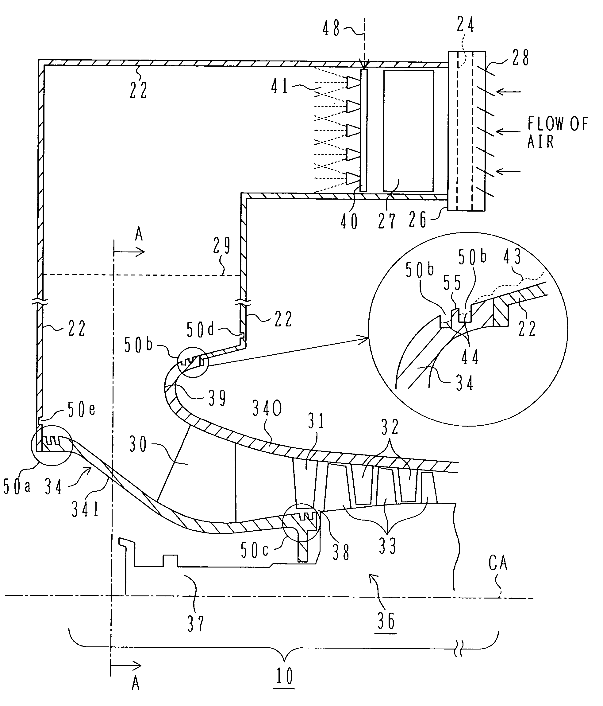
[0027]FIG. 1 is a schematic view showing the construction of the gas turbine system according to one embodiment of the present invention, the view primarily showing an inlet section of a compressor.

[0028]A compressor 10 comprises a rotor system 36 to which compressor rotor blades 33 are fixed, and a casing 34 made up of an outer casing 34O to which compressor stator vanes 32 are mounted and an inner casing 34I. The rotor system 36 and the casing 34 are each constructed to be rotationally symmetric with respect to a center axis CA.

[0029]To the upstream side of the compressor 10, an inlet duct 22 is coupled to take in air (atmosphere) for supply to the compressor 10. The inlet duct 22 i...


PUM


Abstract

A gas turbine system comprises a compressor for compressing air, a combustor for burning the air compressed by the compressor and fuel, a turbine driven by combustion gases produced from the combustor, and a spraying apparatus for adding water to working air at least upstream or in an intermediate stage of the compressor. A rotationally symmetric groove or projection is formed in an inner wall surface defining a channel through which the working air added with the water flows, or in a channel-defining surface of a rotor or a casing of the gas turbine. A larger amount of water can be supplied to the compressor while improving the reliability of the gas turbine.

Description

BACKGROUND OF THE INVENTION[0001]1. Field of the Invention[0002]The present invention relates to a gas turbine system, and more particularly to a gas turbine system suitable for use with water atomization cooling performed by adding atomized water to working air.[0003]2. Description of the Related Art[0004]As one of methods for avoiding a reduction of the gas turbine output attributable to a rise of the atmospheric temperature in the summer season, etc., water atomization cooling performed by adding atomized water upstream of a compressor or in its intermediate stage has hitherto been proposed as described in, e.g., Patent Reference 1 (Japanese Patent No. 2877098), Non-Patent Reference 1 (ASME (American Society of Mechanical Engineer), GT2003-38237), and Non-Patent Reference 2 (ASME (American Society of Mechanical Engineer), GT2002-30562). In such water atomization cooling, it is generally known that an effect of increasing the gas turbine output is enhanced as the amount of water e...

Claims


Application Information

Patent Timeline
Patent Type & Authority Patents(United States)
IPC IPC(8): F02C3/30F02C7/143
CPCF02C3/30F02C3/305F02C7/1435F05D2260/602
Inventor SHIBATA, TAKANORI
Owner MITSUBISHI POWER LTD
Why Eureka
Try Eureka