
Combined lighting and video control system

a video control system and lighting technology, applied in the direction of lighting apparatus, light sources, electric lighting sources, etc., can solve the problems of system constraints, system itself providing no direct assistance, system is still operator-constrained,

Inactive Publication Date: 2012-05-24
ARCHDALE NICK
View PDF4 Cites 21 Cited by
  • Summary
  • Abstract
  • Description
  • Claims
  • Application Information

AI Technical Summary

Benefits of technology

"The present invention relates to a method for controlling lighting and video in live environments. The invention aims to provide a system that reduces the complexity of controlling a large number of control channels in real-time, and allows the operator to dynamically modify the live show in real-time while also allowing the system to adapt to changing conditions during the event. The invention is a method for synthesizing a dynamic lighting configuration in response to user input and environmental conditions. The technical effects of the invention include reducing the complexity of the lighting control system, providing assistance in managing large lighting and video systems, and allowing the operator to dynamically modify the live show in real-time."

Problems solved by technology

This gives the operator complete control but is very time consuming and, with some of the huge systems in use today, may actually be impossible to achieve within the time constraints of the event.
This is an asset in that the lighting performance will precisely match the pre-programmed rehearsal, but is also a constraint as it does not allow the lighting to follow variations in the performance that are common in live events.
However such systems are still operator constrained and the control system itself provides no direct assistance other than allowing the user to override pre-programmed values.
A highly skilled operator familiar with the particular lighting program is always needed and, even then, there are limitations as to what they are physically capable of modifying during a rapidly changing live event.
However, even these systems require extensive set-up by the operator and are limited in their control, autonomy, and expressiveness.
It was complicated and unreliable but hugely influential in that it set out the methodology of subtractive analog synthesis that remains popular to this day.
None of these synthesis techniques have been applied to lighting control in a manner that would allow the combination of mood control and algorithmic programming within the constraints of automated lighting and pixel mapped video.

Method used


Image

  • Combined lighting and video control system
  • Combined lighting and video control system
  • Combined lighting and video control system

Examples


Embodiment Construction

[0074]Preferred embodiments of the present invention are illustrated in the FIGUREs, like numerals being used to refer to like and corresponding parts of the various drawings.

[0075]The present invention generally relates to a method for controlling lighting and video, specifically to methods relating to synthesizing a dynamic lighting configuration in a live environment in response to user input and environmental conditions.

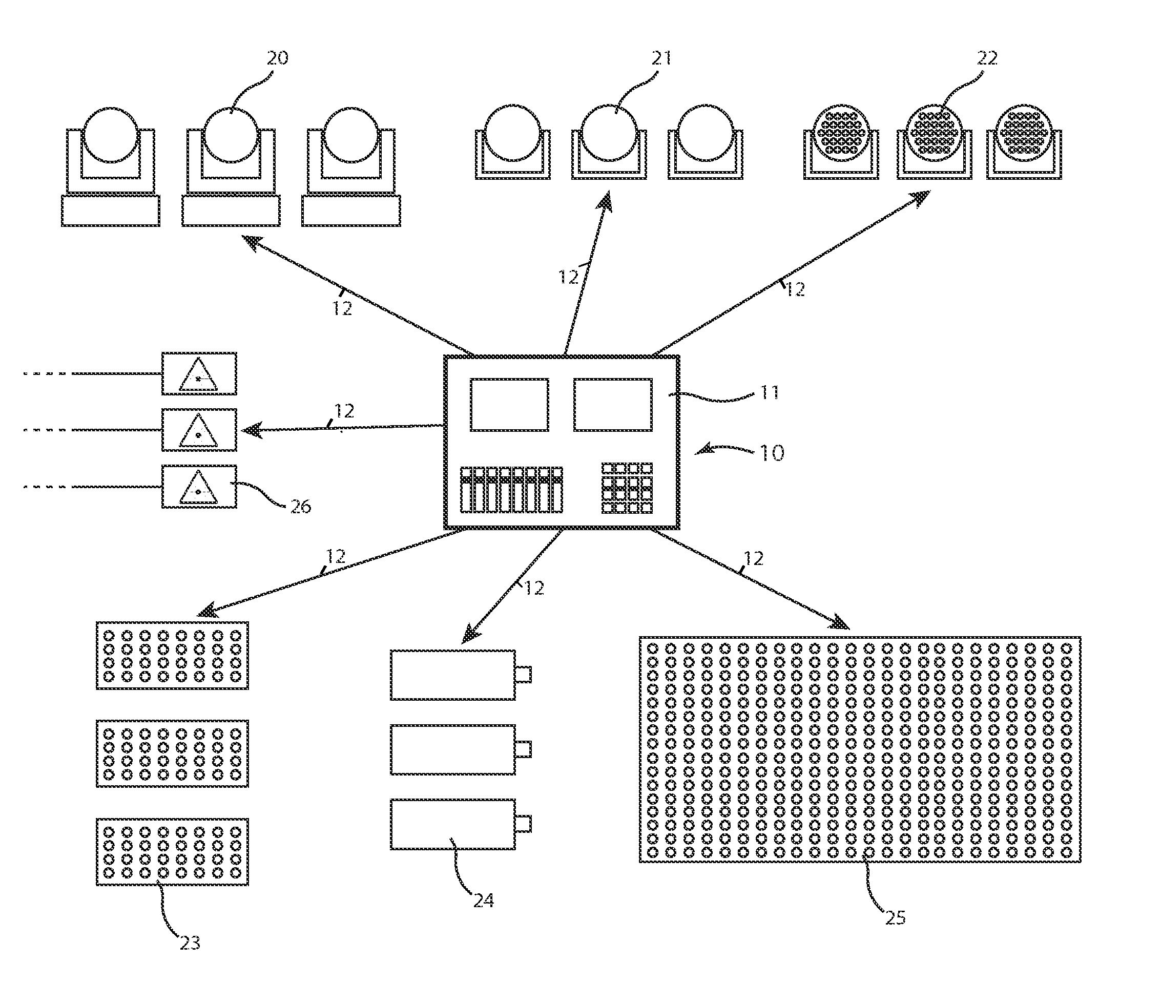
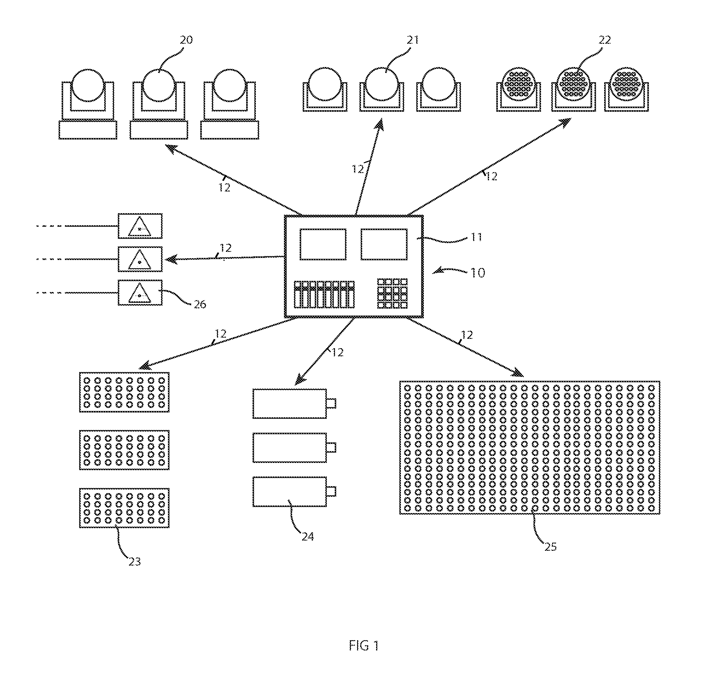
[0076]The disclosed invention provides a parameter driven synthesizer system to generate lighting and video effects within the constraints of automated lighting equipment and pixel mapped video systems as illustrated in FIG. 1. It is designed to interface with all commonly used lighting instruments in the same way as the prior art systems.. The invention imparts no special requirements on either the controlled luminaires or the data links to those luminaires so may be used as a direct replacement for prior art control systems.

[0077]FIG. 5 illustrates a generic sy...


PUM


Abstract

Disclosed is an abstracted lighting control system abstracted based on the lighting canvas rather than the mapping of the location of the luminaires or lighting fixtures.

Description

RELATED APPLICATION[0001]The present application claims priority on Provisional Application No. 61 / 275,906 filed on 23 Aug. 2010 and Provisional Application No. 61 / 454,507 filed 19 Mar. 2011.TECHNICAL FIELD OF THE INVENTION[0002]The present invention generally relates to a method for controlling lighting and video, specifically to methods relating to synthesizing a dynamic lighting configuration in a live environment in response to user input and environmental conditions.BACKGROUND OF THE INVENTION[0003]Live entertainment events such as theatre performances, television and film production, concerts, theme parks, night clubs and sporting events commonly use very large and complex lighting and video arrangements to allow the designers full artistic control over the spectacle being shown to the audience. In order to manage these systems, there has been steady development into highly sophisticated control systems capable of handling thousands of controlled lighting instruments. Examples...

Claims


Application Information

Patent Timeline
Patent Type & Authority Applications(United States)
IPC IPC(8): H05B37/02
CPCH05B37/029H05B47/155
Inventor ARCHDALE, NICK
Owner ARCHDALE NICK
Learn More